Frontispiece
Title: Cordage and cordage hemp and fibres
Author: T. Woodhouse
P. Kilgour
Release date: January 4, 2026 [eBook #77619]
Language: English
Original publication: London: Isaac Pitman & Sons, 1919
Credits: deaurider, Raymond Papworth, and the Online Distributed Proofreading Team at https://www.pgdp.net (This file was produced from images generously made available by The Internet Archive)
CORDAGE AND CORDAGE HEMP AND FIBRES
Frontispiece
PITMAN’S COMMON COMMODITIES AND INDUSTRIES
BY
T. WOODHOUSE
HEAD OF WEAVING AND DESIGNING DEPARTMENT, DUNDEE TECHNICAL COLLEGE AND SCHOOL OF ART;
FORMERLY MANAGER, MESSRS. WALTON AND CO., LINEN MANUFACTURERS, BLEACHERS AND FINISHERS, KNARESBOROUGH;
AUTHOR OF “THE FINISHING OF JUTE AND LINEN FABRICS”; “HEALDS AND REEDS FOR WEAVING, SETTS AND PORTERS”; JOINT AUTHOR OF “TEXTILE DESIGN: PURE AND APPLIED”; “JUTE AND LINEN WEAVING MECHANISM”; “CALCULATIONS AND STRUCTURE OF FABRICS”; “JUTE AND JUTE SPINNING,” ETC.
AND
P. KILGOUR
HEAD OF THE SPINNING DEPARTMENT, DUNDEE TECHNICAL COLLEGE AND SCHOOL OF ART;
FORMERLY MANAGER, BELFAST ROPE WORKS; JOINT AUTHOR “JUTE AND JUTE SPINNING,” ETC.
London
Sir Isaac Pitman & Sons, Ltd., 1 Amen Corner, E.C.4
Bath, Melbourne and New York
Printed by Sir Isaac Pitman & Sons, Ltd., London, Bath, Melbourne and New York
The function of a small article in commercial undertakings is often overshadowed by that of the larger and usually more valuable article, and yet the use of the former is often an absolute necessity for the safety of the latter. This relative value is emphasized in the use of cordage, because the successful prosecution of many industries depends in no mean way upon the utilization of this useful and common commodity.
Some of the various types of cordage are well known to the general public, but the methods employed in their manufacture, the machinery used, and the sources of the fibres are not quite so well known. We trust that these phases are discussed in as brief but as complete a way as is possible in this little book, which we hope will take its own place in the literature of our Common Commodities of Commerce.
We take this opportunity of recording our warmest thanks to Messrs. David Bridge & Co., Ltd., Castleton, Manchester, for loan of blocks; to Messrs. The Edinburgh Roperie and Sail Cloth Co., Ltd., Leith, for assistance and for several photographs; and to Messrs. Landauer & Co., London, for some of the statistics regarding the fibres.
September, 1919.
| CHAP. | PAGE | |
|---|---|---|
| PREFACE | v | |
| I. | INTRODUCTORY | 1 |
| II. | DEFINITION OF CORDAGE AND SOURCES OF FIBRES | 5 |
| III. | CLASSIFICATION OF FIBRES | 16 |
| IV. | THE CULTIVATION OF HEMP | 19 |
| V. | RETTING, BREAKING AND SCUTCHING | 24 |
| VI. | THE CULTIVATION OF PLANTS FOR HARD FIBRES | 31 |
| VII. | THE PREPARING AND SPINNING MACHINERY FOR HEMP AND OTHER SOFT FIBRES | 55 |
| VIII. | THE PREPARING AND SPINNING MACHINERY FOR MANILA AND OTHER HARD FIBRES | 87 |
| IX. | TWINES, CORDS AND LINES | 93 |
| X. | ROPES AND ROPE-MAKING; YARN NUMBERING | 100 |
| XI. | MARKETING | 108 |
| FIG. | PAGE | |
|---|---|---|
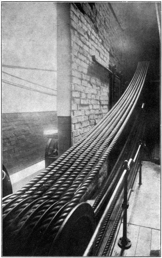
| ROPE DRIVE FOR A MILL SHAFT Frontispiece | ||
| 1. | TWO-YEAR-OLD SISAL PLANT | 6 |
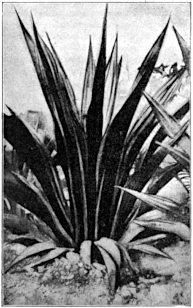
| 2. | AGAVE AMERICANA | 8 |
| 3. | TRANSVERSE SECTION OF A LEAF OF AGAVE AMERICANA | 10 |
| 4. | PHOTOMICROGRAPH OF A SECTION OF FIBRES OF AGAVE AMERICANA | 11 |
| 5. | PHOTOMICROGRAPH OF FIBRES OF AGAVE GROWN IN MEXICO SHOWING OXALATE OF POTASH CRYSTALS | 12 |
| 6. | GROUP OF HEMP PLANTS | 13 |
| 7. | CROSS-SECTION OF PLANT | 13 |
| 8. | LONGITUDINAL VIEW OF COTTON FIBRES | 15 |
| 9. | CROSS-SECTIONAL VIEW OF COTTON FIBRES | 15 |
| 10. | MANILA FIBRES: ORDER OF GRADING | 35 |
| 11. | BRIDGE’S “ACME” GRAVITY PATENT SISAL BREAKER | 38 |
| 12. | BRIDGE’S “CLIMAX” PATENT SISAL DECORTICATOR | 40 |
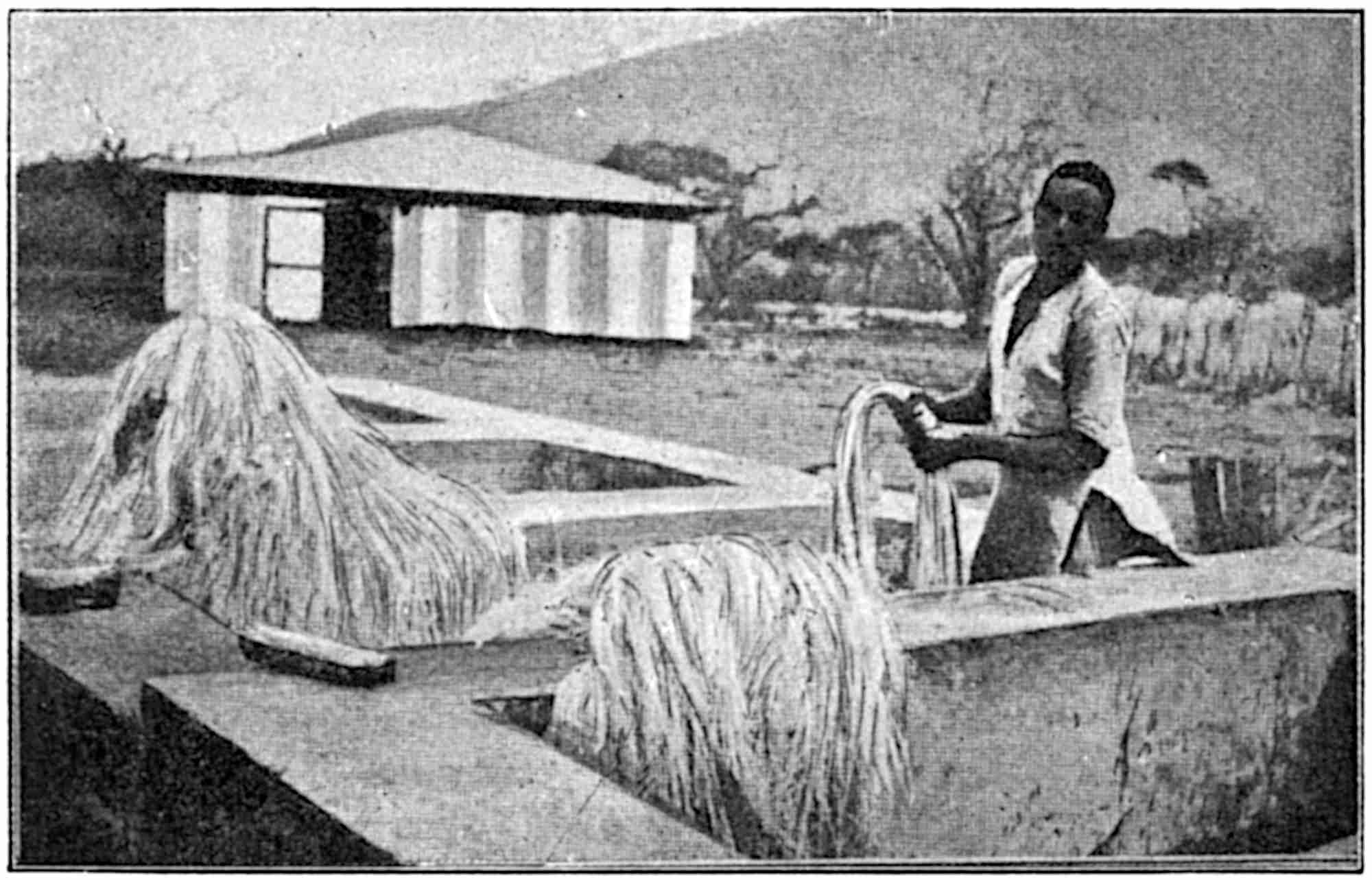
| 13. | WASHING TANKS | 43 |
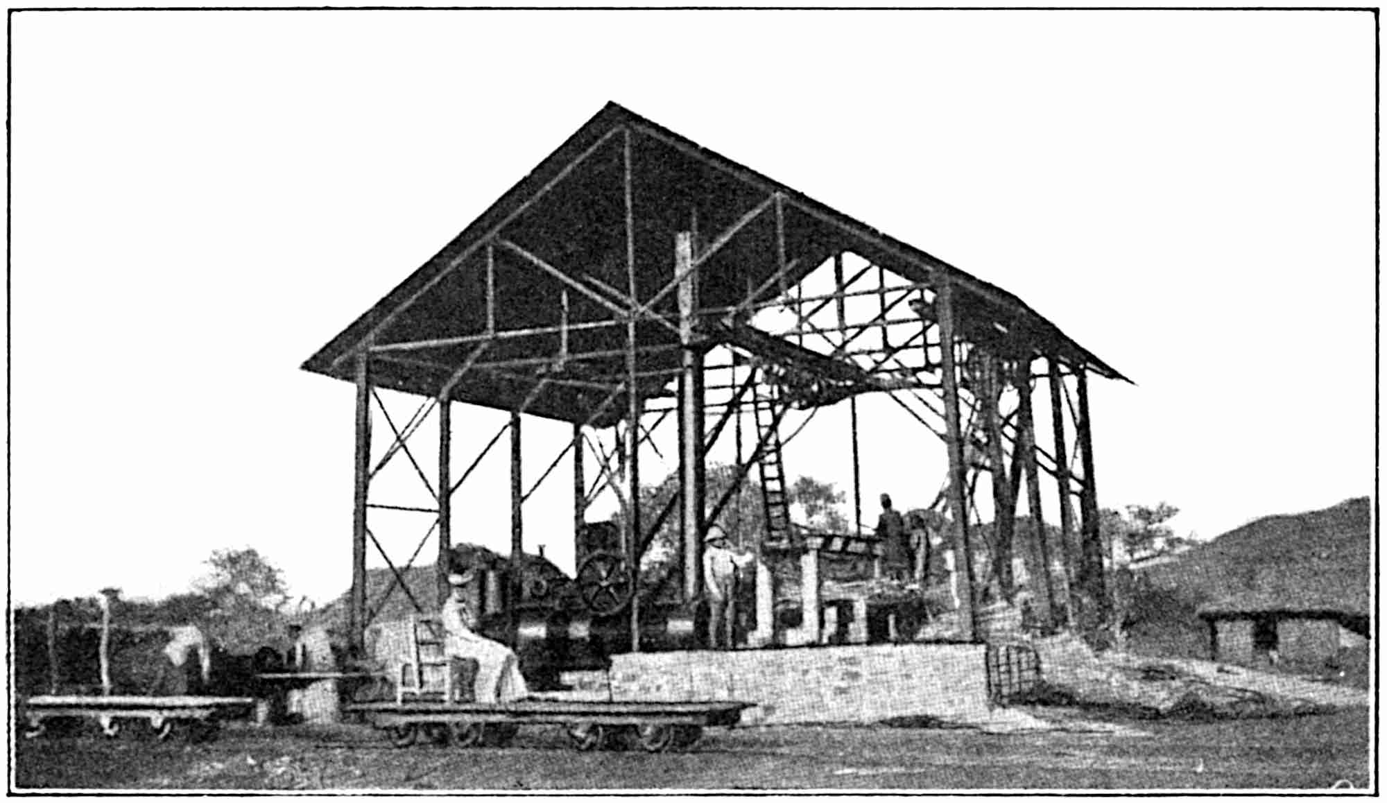
| 14. | HOUSING FOR POWER PLANT | 43 |
| 15. | CUMMINS’S PATENT HORIZONTAL HYDRAULIC BALING PRESS | 43 |
| 16. | MAURITIUS FIBRE PLANT | 47 |
| 17. | BALES OF MANILA, NEW ZEALAND AND SISAL FIBRES | 54 |
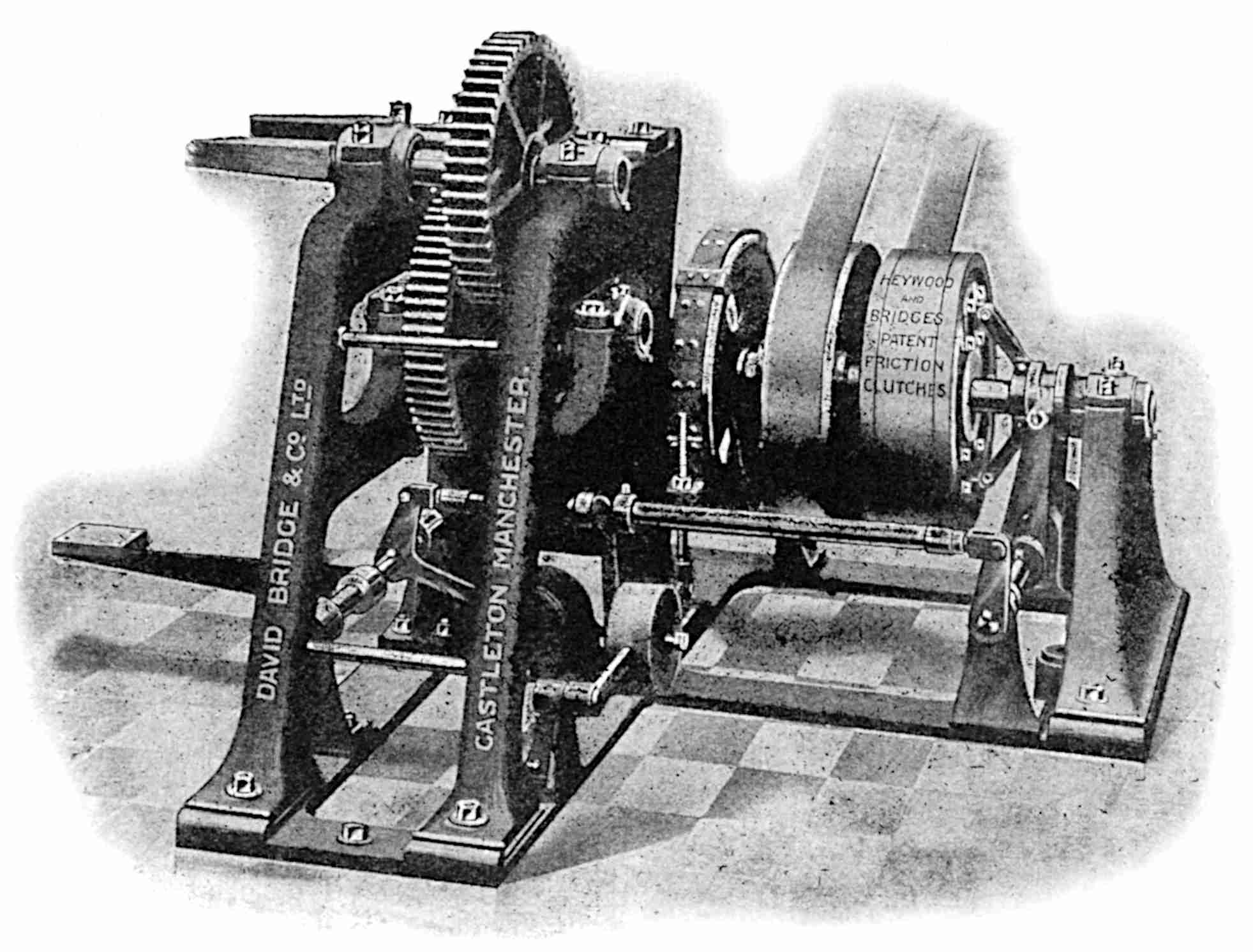
| 18. | BREAKING MACHINE | 60 |
| 19. | HACKLING MACHINE | 62 |
| 20. | SPREAD BOARD | 69 |
| 21. | BREAKER AND FINISHER CARDS | 74 |
| 22. | DRAWING FRAMES | 80 |
| x23. | ROVING FRAME | 81 |
| 24. | DRY SPINNING FRAME | 84 |
| 25. | HACKLER AND SPREADER | 87 |
| 26. | INTERMEDIATE MACHINE | 89 |
| 27. | AUTOMATIC SPINNING MACHINE | 91 |
| 28. | DRYING BLEACHED YARNS | 93 |
| 29. | ROPE-MAKING (HOUSE MACHINES) | 101 |
| 30. | LAYING OF A FOUR-STRAND CABLE-LAID ROPE IN THE ROPE WALK | 105 |
| 31. | VIEWS OF LARGE AND MEDIUM-SIZED COILS OF ROPE | 106 |
CORDAGE AND CORDAGE HEMP AND FIBRES
Records of civilization are incapable of furnishing the era when the equivalent of strands or cords were first used, singly or collectively, for the purpose of holding two or more articles securely in position. But, although it is impossible to fix a period, one might safely say that the original material which served the purpose was some kind of light twig or lanceolate leaf, and that its appearance when in use as a binder strip differed little if at all from its appearance in the natural process of growth. Even at the present day some of these runners are still used, notably with others the rattan canes for binding bales of manila fibre and other purposes.
The wants of prehistoric man would be very few indeed, but, although he was accustomed in many climates to make use of very scanty clothing or covering, and, in many cases, was practically without any covering, it is obvious that it would be necessary to provide himself with food—the first essential condition to life. In his efforts to secure the necessary food-stuffs, animate or inanimate, it is safe to conclude that some type of ribbon-shaped vegetable material would be necessary or desirable at an early stage, and probably at the same time or a little later period sinews of different kinds would be brought into use.
2As years rolled on, further uses would undoubtedly be found for various kinds of fibrous material, and more improved methods would be applied in adapting the vegetable matter and the like to the purposes intended, as well as more care exercised in the selection of the materials. Some of the characteristics which are essential in practically all binders or tying strips are length, strength, pliability and a tendency to resist atmospheric influences and other natural agents.
The gradual development of civilization, and the gradually increasing demand for suitable substances to be used as binders and for various other purposes would naturally lead to improvements in the utilization of fibrous and other suitable plants, and ultimately to more or less scientific methods of treating these plants with the object of removing the objectionable constituents which are useless for cordage purposes, and of retaining those parts which are considered to be most suitable for the purpose in view.
A complete description of the evolution of modern cord and cordage is practically impossible, for the simple reason that there is no full record of the efforts of many of the earlier pioneers in the various stages, and it is quite possible that many early and praiseworthy improvements have been forgotten or overshadowed, or perhaps absorbed, by the more modern and more elaborate methods which are now indispensable for the successful prosecution of this important branch of the textile industry.
The separation of fibrous material from various kinds of plants is by no means of modern origin, for the great antiquity of yarns which have been spun from vegetable and animal fibres is universally acknowledged. Reference to the process of preparing flax for the purpose of 3spinning appears in Exodus ix, verse 31, while the first Biblical reference to thread—one of the technical names for a continuous length of prepared fibrous material—is in Genesis xiv, verse 23: “That I will not take from a thread even to a shoe-latchet.” Again, another early reference in Chapter xxxviii refers to a scarlet thread, an indication or suggestion that the art of dyeing was also known at this early period in the early Biblical history.
Herodotus records garments made from hemp by the Thracians, and to the present day hemp is largely cultivated in the vicinity of the lands occupied by the descendants of this ancient race.
Moschion, whose writings appeared before the Christian era, states that the “great ships of Syracuse which were built by command of Hiero II were supplied with hemp and ropes from the Rhone districts. Hemp was brought from Colchis to the ports of the Aegean Sea by the merchants who were connected commercially with the north and east coasts of the Euxine through their Milesian colonies.”
Pliny also records the use of hemp for ships, and states that it was in common use among the Romans in the first century for ropes and sails, as well as for other purposes.
The more or less uncertain knowledge of practically all the earlier attempts at the solution of fibre extraction renders it impossible for us to bridge the gap between the time when crude primitive methods were practised and that which ushered in the more perfect methods described by Pliny in the first century—methods which, in certain cases, have varied little since this early period, and which are practised with a high degree of success. We may, therefore, leave this interesting period to the researches of students in history, 4and enter upon the description and illustration of the various plants from which fibre is extracted, and the actual processes which such fibre has to undergo before it is ready for the market in one or other of the well-known types of cordage.
The definition of cordage usually takes the form of “a quantity of cords or ropes as the rigging of a ship, etc.,” but in commerce the word has a more elastic meaning, and, in general, may be said to include all kinds of continuous strands or the like which are not intended to be woven into cloth or to be knitted into hosiery. Differentiation occurs, however, for one often finds the phrase “Ropes, Cords and Twines” as referring to special types of cordage, while further subdivision occurs when one includes the many types of finer material such as lines, sewing thread, and the like. And when one considers that the various articles which are included in the generic term cordage have a range from ropes of 9 or 10 in. in diameter to fine threads of not more than perhaps 1/60th of an inch, and for which a very large number of different kinds of fibres are used, some idea of the immense variety can possibly be formed.
From whatever source a vegetable cordage fibre is derived, it is necessary to eliminate more or less of the substances which are closely connected with it in the plant, in order that the comparatively pure fibre may be spun into thread form with the maximum of strength and production, and the minimum of difficulty and waste. In this respect it is quite likely that an animal fibre such as wool would be more easily separated than any other known fibre. Wool, however, is rarely used for cordage purposes, although hair, which approximates to wool, is used for certain types of cord. There are certainly many types of wool ropes used for decorative purposes, but, in general, this most valuable substance 6is, for obvious reasons, unsuitable for the usual kind of cordage, and hence wool will not be discussed in this work.
The fibres from the leaves of certain tropical plants may be separated with a little more difficulty than that which is experienced in the operation of shearing a sheep, but these fibres are hidden, and even when found originally, great difficulty would be experienced before a continuous thread could be made from them. It is quite probable that a natural process of disintegration would disclose these vegetable fibres to primitive man, and lead to their ultimate utilization for various purposes. Or perhaps the gradual wear and tear of the leaves used, either loosely or bound in some crude form, as floor-covering would result in the discovery of the fibrous layers. It is the remarkable advance in mechanical science which has made the production of a continuous thread from such fibres a possibility for industrial purposes.
Long before continuous spinning was invented, however, it would be desirable to extract the valuable fibrous material from its bed of vegetable matter because the latter is, in general, quite unfit for the purposes which the fibrous material has to perform. This remark applies not only to the fibres which are extracted from leaves, but also to those valuable fibres which are embedded in the bast layers of the stems of certain plants.
We might now with advantage illustrate by means of photographic reproductions of plants, and photomicrographs of sections, the three sources from which vegetable fibres are obtained to be utilized in the manufacture—or spinning as it is technically called—of the world’s supply of cordage.
A typical example of a leaf plant from which one 7type of textile or cordage fibre is extracted is illustrated in Fig. 1. This particular example is designated as a “Two-year-old Sisal Plant.” It is 49 in. high, and was grown in the Voi district, British East Africa. Sisal is the commercial name of the fibre obtained from such plants, while the botanical name of the plant is Agave 8Rigida, variety Sisalana; it is sometimes, though erroneously, termed the Americana.
A recently suggested nomenclature of the Agave and other plants, from which sisal and similar fibres are extracted, is due to Professor Lyster Dewey of the United States Department of Agriculture—
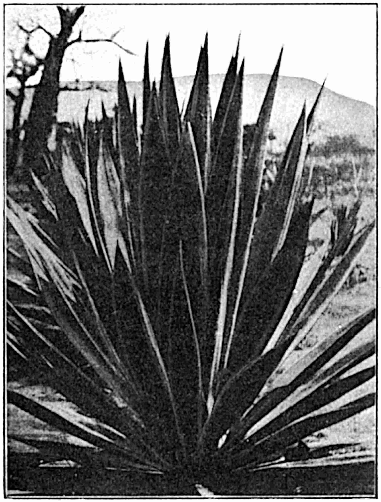
(1) Agave Fourcroydis of Yucatan; this plant yields 990 per cent. of the sisal fibres exported from all countries. The leaves bear marginal spines as illustrated in the Agave Americana shown at A, Fig. 2: the plant was formerly known as Agave Rigida, variety Elongata.
10(2) Agave Sisalana grown for use by the natives of Central America and South Mexico, but not much exported.
(3) Agave Cantala. This is the “Maguey” plant of the Philippine Islands, and is grown in limited quantities in Java and India.
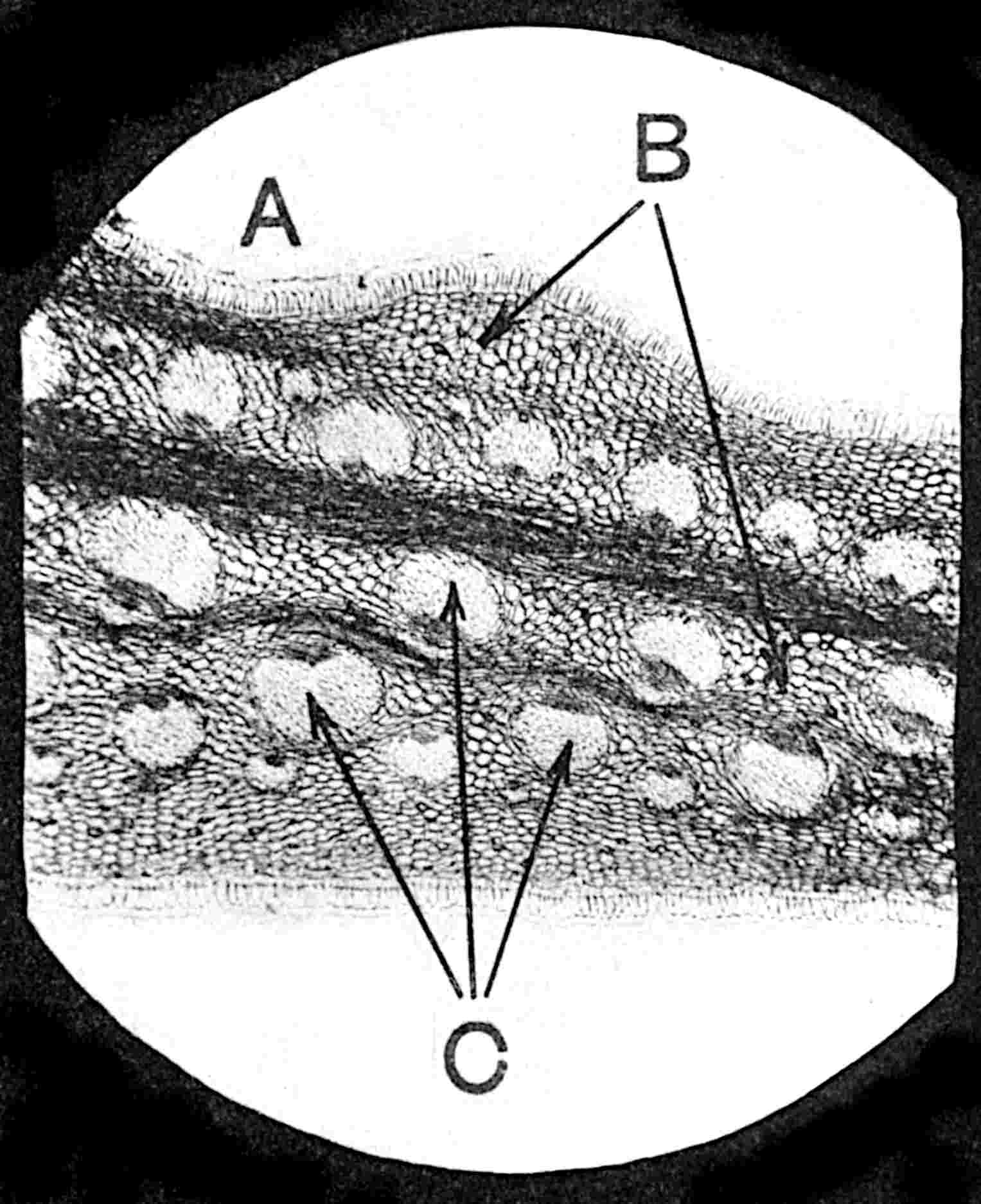
When a thin slice or fine transverse section of one of the leaves of such a plant is mounted, and its appearance magnified by photomicrography, the structure of the leaf is shown to be similar to that illustrated in Fig. 3. The upper and the lower outer surfaces or cuticle A resemble greatly the whipped edges of blankets. 11These surfaces, and all the pulp-like matter lettered B, must be removed, either by manual or mechanical means, in order to separate or extract the groups of fibre some of which are denoted by the letter C. A still further enlargement of a few of these groups of fibrous material appears in Fig. 4.
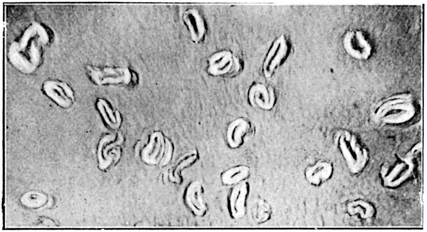
12A photomicrograph of two fibres of a type of Agave grown in Mexico is shown in Fig. 5; it is interesting because it depicts the formation of crystals of Oxalate of Potash. The presence of such crystals makes the fibre unsuitable for cordage purposes, but it may be used in the manufacture of coarse brushes.
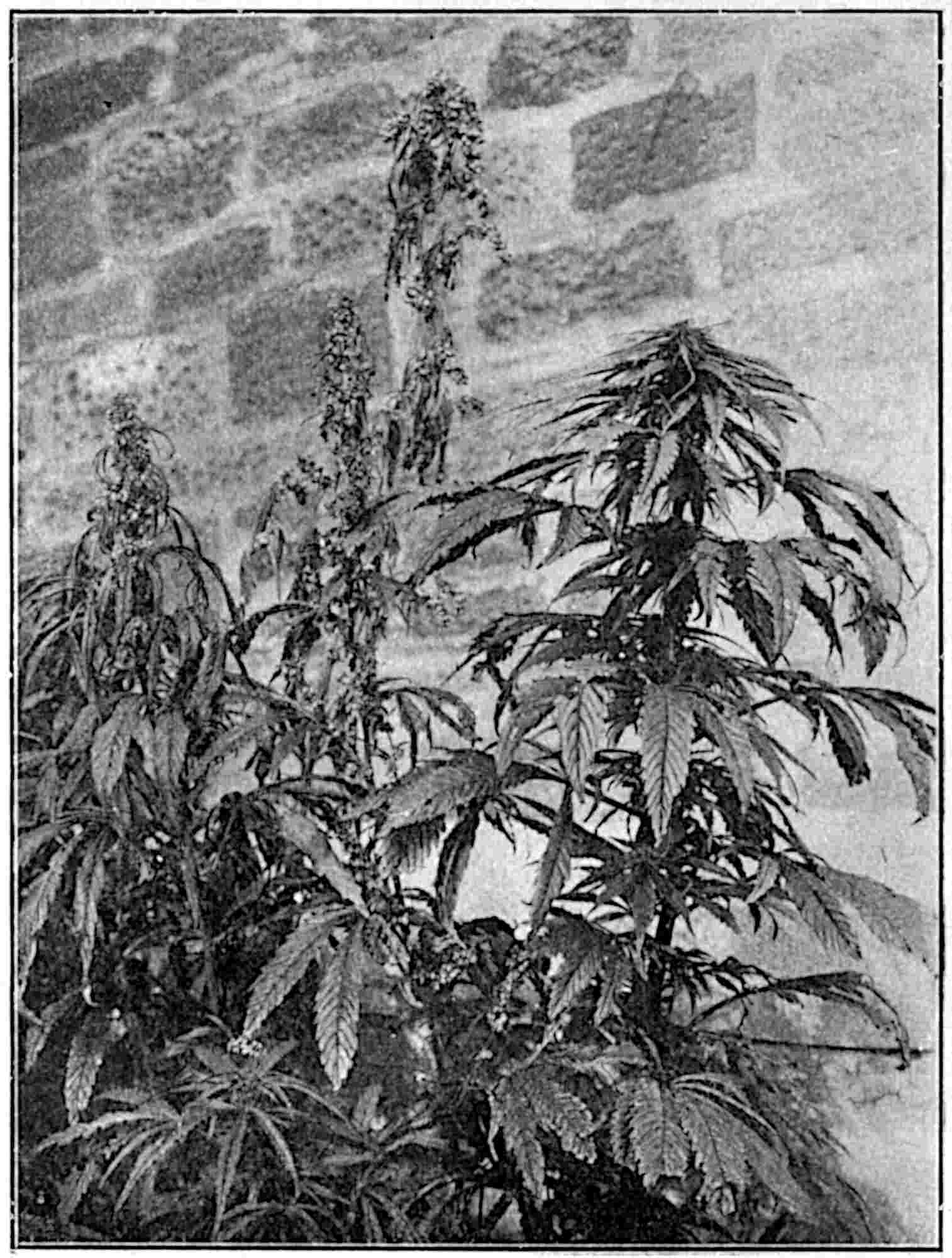
13The second source from which fibre is extracted is that from the stems of plants such as flax, hemp, jute and the like. A photographical reproduction of a group of hemp plants grown by the Authors appears in Fig. 6. A female plant is illustrated on the right, while the remaining two which are taller are male plants.
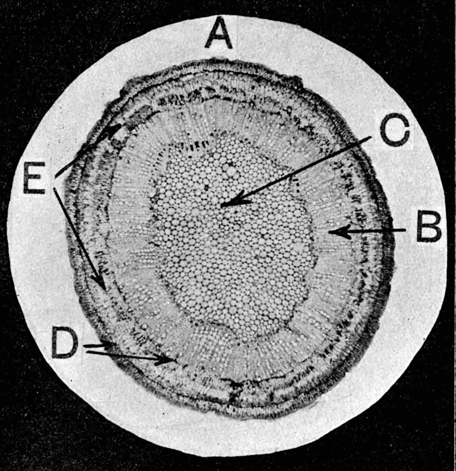
A thin cross-section cut from the stem of such a plant 14exhibits the characteristics in Fig. 7, in which A is the cuticle or outer bark, B is the woody part, and C the pith. The fibrous layer is between the two dark circles D, and a few groups of fibres in this layer are indicated by the letter E. Here, again, a considerable amount of extraneous matter must be separated from the bast layer, and when separated, the latter appears in the form of long ribbons. The cuticle and bast layer were originally stripped from the plants; the former were then placed in the mouth so that the saliva could aid in the separation of the fibres from the bark, and permit of a finer reduction of the fibrous layer to produce finer threads. And although at the present time this method is practised for thread making in many primitive communities, it need hardly be said that much more efficient methods have long been practised for commercial 15purposes, such methods being known by the technical terms “retting,” “breaking,” and “scutching.”
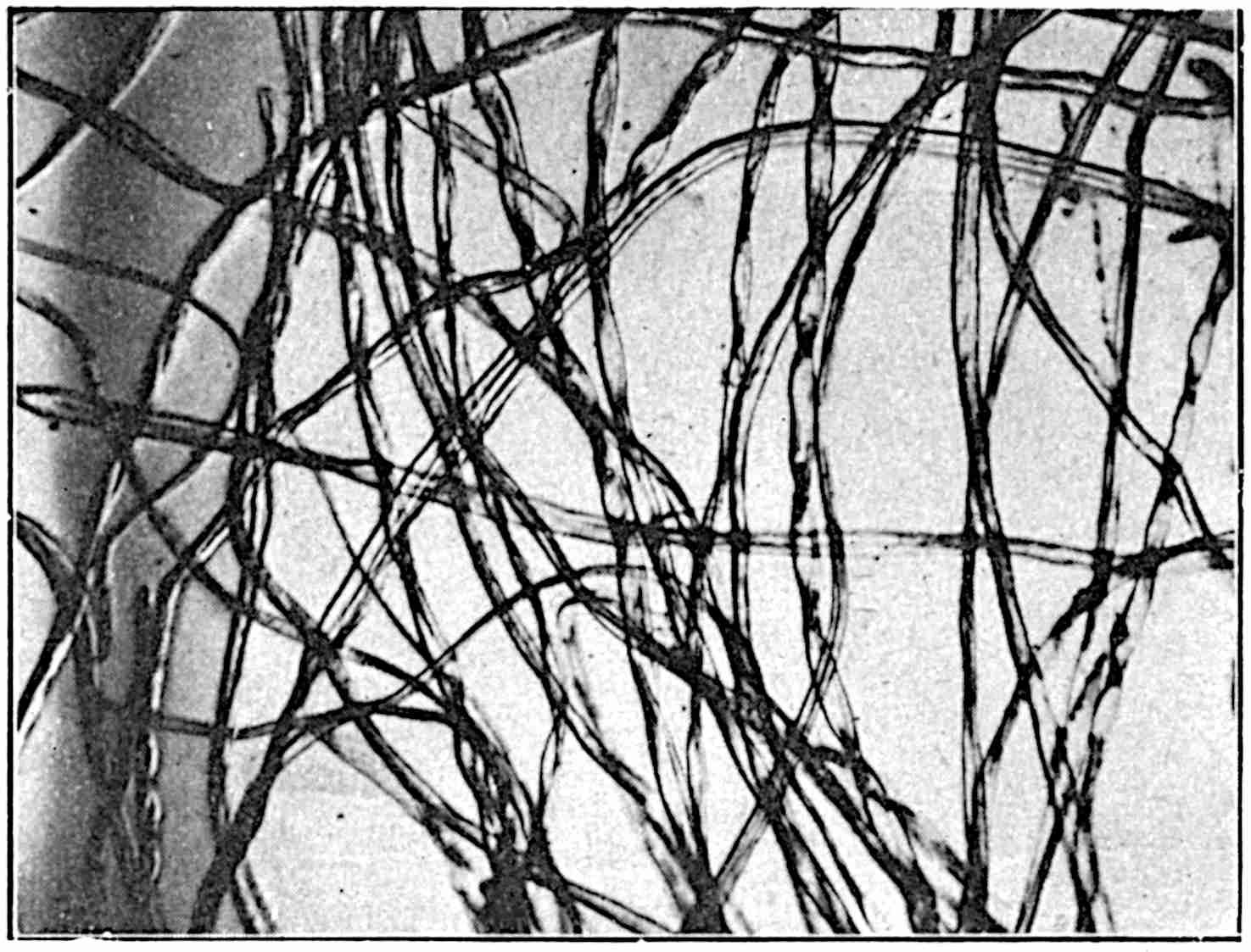
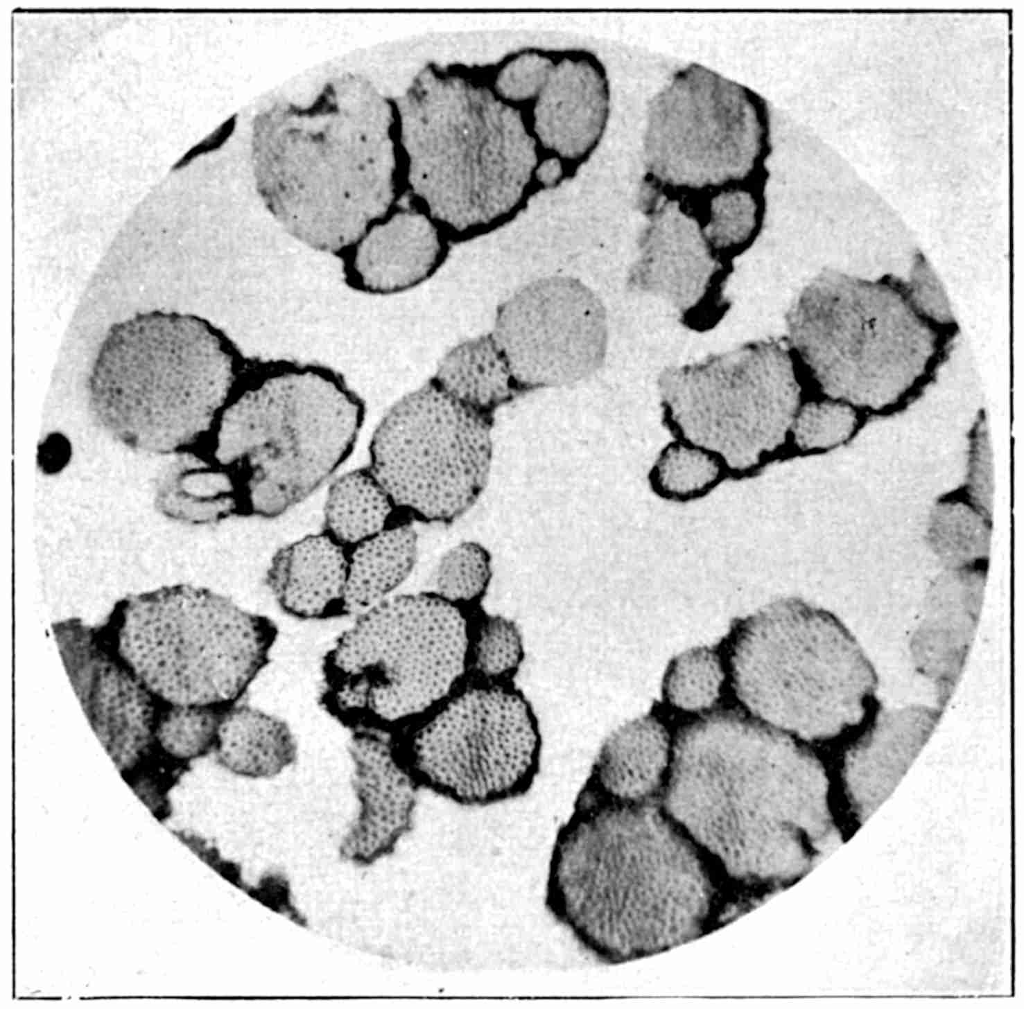
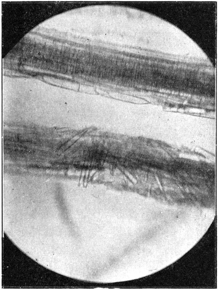
The third source of vegetable fibres is the cotton plant Gossypium, the white fluffy fibres being obtained from the pods or bolls. The operation of cotton picking which is often referred to consists of removing this white fluffy mass from the pods in which also the seeds are located. Cotton fibre is unlike the two previous classes of fibre because its method of growth is different. The other textile fibres are composed of bundles of plant cells, whereas the fibres of cotton are individual cells; they form as it were individual hairs on the seed, and in drying flatten and also assume a twisted and crinkled condition as exemplified in Fig. 8, which illustrates the longitudinal characteristics of several fibres. Fig. 9 shows the sectional enlargements of a few fibres. This structure of the cotton fibre is a very valuable property, since it not only assists in the binding of the fibres into a thread, but also gives a resiliency and spring to ropes manufactured from it which is most useful in driving; this property makes cotton almost indispensable for the construction of the smaller sizes of ropes for driving purposes.
Cordage fibres which are used at the present time are naturally of greater variety than those which were utilized for similar purposes in the early periods of history, for records of those used in such early periods appear to indicate only hemp and flax. As already stated, wool would not be used to any great extent, but, after methods had been evolved for spinning a continuous thread from fibres such as hemp and flax, it is highly probable that the cotton fibre would also be used in the making of cords and ropes.
Authentic records point to the fact that the cultivation of flax plants for fibre was practised in Egypt from 5,000 to 6,000 years ago, and hence it is quite possible that hemp plants would be grown under similar conditions and for suitable purposes; moreover, if the hemp fibre were proved to be suitable for cordage purposes, it is not difficult to believe that the cultivation of this important plant in suitable districts would become as universal as that of flax.
Another reason which suggests the early use of hemp as a cordage fibre is the universality of its presence in most eastern countries as a vegetable product. It is at present cultivated in most European countries, and especially in Russia, Italy, Austria-Hungary, Serbia, France and Germany. It is also found on the East and West coasts of Africa, in many of the States of America—particularly in Kentucky—as well as in India, China and Japan.
If the climate is comparatively moist, with a period 17of mild temperature and a suitable soil, the hemp plant can be successfully cultivated for fibre; it is cultivated in India and in most of the tropical countries for the production of a liquor which the natives consume in much the same way as intoxicating liquors are consumed in temperate countries.
True hemp is a plant which grows wild in Central Asia, but must be cultivated in practically all other areas. It is an annual, and requires a rich soil with a subsoil capable of retaining sufficient moisture to promote the growth during periods of dry weather. If otherwise, the growth of the plants would be checked during this dry period with a consequent deficient yield of fibre.
With the gradual development of trade, and the introduction of new kinds of fibre to be used for cordage, an extended meaning has been applied to the word hemp, but, unfortunately, the word has been applied rather loosely to many types of fibre which are used for rope-making. Thus, one frequently hears the following names in reference to different fibres—
whereas the real hemp is usually designated as—
To differentiate between these different fibres, and so provide a better classification and conception of the terms, it should be clearly understood that the proper hemp fibres, e.g., Russian, Italian and Indian, are 18obtained from the plant Cannabis Sativa, and that the fibres are located in the bast layers of the plant stems as exemplified in Fig. 7. The fibres are extracted from these layers in the same way as the fibres of flax and jute are extracted from similar layers, that is, by a process technically termed “retting.” Such fibres are called soft fibres in contradistinction to hard fibres to which class Manila, Sisal, New Zealand, Mauritius and Bowstring fibres belong. The hard fibres are located in the leaves or in the leaf stalks of plants; typical examples of the general appearance of such plants and the internal characteristics are illustrated in Figs. 1 to 5.
The botanical or scientific name for hemp is Cannabis Sativa, order, Moraceoe, sub-order, Cannaboidae. The plant grows wild in Central Asia, but is cultivated in many tropical and temperate regions of both hemispheres. From a cordage point of view the fibre is, naturally, of most importance, but, incidentally, it might be mentioned that the seed is used as a food for birds, and oil is extracted from it; in addition, in tropical countries, a resinous juice exudes from the stalks, leaves and flowers which is made into a violent intoxicant.
The plants in general attain a height of from 4 to 8 ft. or more, and in exceptional cases, such as under good cultivation in suitable soil, approach 20 ft. in height. The leaves are five to nine lobed with serrate margin. The plants are dioecious and the flowers are yellowish-green, small and inconspicuous; the male flowers are numerous and produced in drooping panicles, each flower of five segments; the female flowers are fewer in number, on spikes, single leaf, single ovary, with greyish-green to brownish-grey seed, and rich in oil. The matured stems are usually hollow, and the bark layer very fibrous throughout the whole length of the stem.
The plant readily adapts itself to great changes of climate, and, as already stated, is found in all climates, from the tropical ones of India and China to the frozen regions of Northern Russia. It is adversely affected, however, in the earlier stages of its growth by frost, 20and always requires a moderately strong sunny period during its growth. It is cultivated in the temperate climates chiefly for its valuable fibre, but a serviceable fibre may be obtained from the plants which are grown in tropical countries.
The most important fibre-producing areas are Russia, Italy and Austria-Hungary, but it is produced in other countries, notably those mentioned below, as well as in Turkey, China and the Southern and Western areas of the United States of America. The Italian fibre is the best of all for fine work, while the Russian fibre, which has a special affinity for tar, is the most satisfactory for use in the manufacture of heavy cordage for maritime purposes.
The approximate annual production of hemp from fourteen different countries appears below—
| Russia | 400,000 | tons |
| Italy | 80,000 | „ |
| Hungary | 50,000 | „ |
| India | 36,000 | „ |
| Siberia | 22,000 | „ |
| Austria | 18,000 | „ |
| France | 15,000 | „ |
| Japan | 8,000 | „ |
| Serbia | 8,000 | „ |
| Caucasus | 5,000 | „ |
| Poland | 4,000 | „ |
| Bulgaria | 2,000 | „ |
| Germany | 2,000 | „ |
| Roumania | 1,500 | „ |
The successful cultivation of hemp requires a rich, deep and well-worked soil with a large amount of humus. Alluvial soils are well adapted for the purpose. The strong loam soils of Italy are typical of the best. In all cases a good supply of moisture is necessary, otherwise the crop would be short and stubby and ill adapted for the production of fibre.
The land should be well prepared by deep ploughing, 21and followed by rolling and harrowing to produce a level and uniform seed bed. The roots of the plants will penetrate into the subsoil if the land is well ploughed, but waterlogged land is unsuitable. A liberal supply of manure is essential owing to the vigorous growth of the crop, and while farmyard manures are the best, the stalks of a leguminous crop may be ploughed in. Manure from animal slaughter-houses is very suitable, and all refuse from the previous hemp crop should be returned to the land. Since the hemp fibre contains a large amount of lime and phosphates, it may sometimes prove advantageous to use dressings which contain these substances.
The seed should be selected with care, and should be tested for its powers of germination. Stored seeds are liable to heat and lose their vitality, and immature seeds are also unsatisfactory. Indian and Chinese seeds are often mixed with home seed. In temperate climates sowing should take place as early in spring as possible, but after the night frosts have passed. The early spring rain and sun are very beneficial, and the foliage which appears moderately early helps to conserve the moisture in the soil as the heat of the sun gets more intense.
The amount of seed to be sown depends upon the type of fibre desired; thus, one bushel of seed per acre for coarse fibre to three bushels per acre for fine fibre are the approximate quantities, and the seed may be sown broadcast by hand, or by machines into drills about 6 or 7 in. apart. In all cases the seed should be well covered to prevent ravages by birds, hence, it is usual after sowing to harrow and roll the fields again for the above purpose, as well as to prepare a level and uniform bed for the germination of the seeds.
Where the land is cultivated with the production of seed as its main object, the seeds should be sown thinly 22and wide apart, say, in drills or rows from 6 to 7 ft. apart, so that the plants will branch extensively and thus provide facilities for a profusion of flowers. The male plants are pulled after the bloom is shed, but the female plants are allowed to mature under the best conditions so that a large crop may result. Great care must be taken in harvesting and in storing the seed; provision must be made to prevent the deterioration of seed through a process of heating. The average yield of seed per acre is about thirty bushels, but in exceptional cases as many as sixty bushels may be obtained.
Under satisfactory conditions the young plants should appear in from seven to twelve days, after which it is necessary to thin them out and to remove the weeds. While the plants must be wide enough apart to facilitate good growth, there should not be too much space between them when grown for fibre, or branching out will result. If a field has become troublesome with weeds, no crop will eliminate them as quickly as that of hemp.
If desired both male and female plants may be harvested at the same time, but it is often considered advisable to harvest them separately. It is as well to make most of the mixed crop if the labour is available. The male plants may be cut or pulled when the flowers attain maturity or a little after, and when the leaves are changing colour from green to brown. The female plants being shorter may be allowed to remain for about four weeks when the seeds are beginning to ripen.
The yield of fibre per acre of land cultivated is influenced by several conditions, but on good lands under satisfactory conditions of cultivation, an average of 6 to 7 cwt. may be relied upon, and in many cases this quantity is easily exceeded.
After the plants are harvested, a number of minor 23operations take place in different districts before the plants are subjected to the important process of “retting” or rotting. These preliminary operations are mostly to reduce the weight of the plants and to discard undesirable matter which happens to be easily detached, as well as to secure uniformity. Thus, the tops and roots may be cut off, and the leaves stripped or beaten off, while after the plants have been dried, they may be arranged according to length and thickness. They are then tied up into bundles of suitable bulk for the operation of retting.
The retting operation is that process which converts the constituents of the stems into that condition which will enable the bast layer, see Fig. 7, to be separated easily from the remaining parts of the stem. In all fibrous plants of the type illustrated in Figs. 6 and 7, a retting process is conducted in which the plants are either submerged in water, called “water retting,” or spread on lands adjoining the cultivated areas to undergo what is termed a weathering action, or “dew retting.” Water retting is the more satisfactory and gives the better results, and, in the hands of experienced operatives a more rapid production of fibre of the better grades.
The submersion of the plants, caused by placing stones, clods or the like on to the bundles, may be in slowly-running rivers, in which case the bundles are kept intact in crates moored to the bank, or a similar submersion may be conducted in a series of tanks or ponds. In the latter case a supply of water may be allowed to enter and leave the tank, and the plants are kept there until the operation is complete. Stagnant water acts quicker on the plants than does running water.
The retting action is a process of fermentation, and the amount of active bacteria can be regulated by the temperature and rate of movement of the water. Flax retting in the river Lys, near Courtrai, is the finest system known at present, and its value is due to the slow rate of movement of soft water which is favourable to the production of the retting bacteria; 25the adaptation of a similar system to this where the water supply is suitable will give high-class results.
Fermentation starts soon after the plants are submerged, and the rate of fermentation depends upon the temperature of the air and water; its progress is identified by the presence of air bells on the surface of the water. As the operation proceeds, the bundles have a tendency to rise to the surface, and hence extra weights are added to keep them submerged. When the formation of air bells ceases, the operatives carefully examine and test the stems to ascertain the progress of the operation; they usually strip off part of the bast layer, see Fig. 7, from the wood or core, and their judgment of the correct stage of retting is determined by the ease with which this separation is effected. Great skill is required here, or rather ripe experience, for if the retting is not complete, a portion of the woody matter goes forward with the fibre, while if the stems are over-retted, the fibre is weak; in both cases, a faulty judgment causes trouble in the actual manual or mechanical processes which follow.
Other methods of retting are adopted in different countries, and even in certain districts of those countries where the above system is in vogue. It will be understood that the choice of any system will depend largely upon local circumstances, and in all cases, other things being equal, the method adopted will be that which will yield the largest quantity of hemp fibre at the least cost.
The characteristics of the fibres are typical of the countries in which the plants were grown, and of the processes of retting. It will be almost invariably found that the best fibre is the result of the most elaborate and careful methods of cultivation and retting, together with the equally careful and efficient subsequent processes of breaking and scutching.
26It need hardly be said that the above elaborate and costly methods are adopted only for the very finest grades of fibre; they would not be attempted in the case of those plants which grow and ripen so rapidly in some tropical countries, and in which a short, harsh fibre only is obtained; for such plants the cheapest and simplest methods of extraction are practised.
Many praiseworthy attempts have been made, and others are still in progress, with varying degrees of success, to extract the fibre quickly. None has yet been able to supplant the above-described costly, lengthy and laborious process, but with modern science, machinery and experience, one might expect that some brilliant genius will ultimately solve the problem. Many industrial problems have been solved by the joint action of experience and applied science, and one might therefore hope to see a great simplification of the present hazardous operation of retting.
The successful introduction of a machine or a system of machinery which would pull, strip and clean hemp and allied plants and fibres on the field of growth would not only open up new fields of cultivation, but would increase the wealth of our country by millions of pounds; it would do much to prevent the depopulation of the rural districts and so help to preserve the hygienic conditions of our large towns.
The retting operation completed, the stems are washed and spread on grass land, if available, or stooked like grain and allowed to dry thoroughly. It is acknowledged to be advantageous to allow the stems to remain a few days on the grass, for after this exposure the fibre is more easily and efficiently separated from the other constituents of the bast layer.
The ribbon-shaped layer may be about 3 ft. long in the shorter Russian grades of hemp, but up to 15 ft. 27in length in the Italian grades. The colour varies from grey and brown to a rich cream and almost white in the finest grades.
The ultimate fibres are large and somewhat irregular in shape; they vary in length from 0·2 to 2 in., with an average length of about 1 in., while the diameter is only about 1/1000 or 0·001 of an inch.
Breaking and Scutching.—Various methods are adopted to separate the bast layer from the central or woody part of the retted and dried stems of hemp, but in all cases the operation thus involved is termed “breaking.” The central woody part has to be broken into a great number of short lengths, and this is done in some districts by exceedingly simple apparatus, and in other districts by modern breaking machines. Perhaps the simplest apparatus which is used for this purpose consists of a series of Δ-shaped wooden bars arranged horizontally in the form of a grid, and into the cavities of this row of bars fits another group or series of similar bars but inverted. The latter group is hinged at one end and provided with a handle at the other.
When the handle and the upper set of bars are raised, a few hemp stems are laid across the fixed lower bars; the handle is then pressed downwards, and this causes the stems to be squeezed and broken between the two sets of bars. By repeated blows with the upper bars, and lateral movements of the stems, it is evident that the woody core would be broken, and this is done without damaging the fibrous layer. A treadle may be attached to the handle end of the hinged grid and thus leave both hands free to manipulate the stems and to remove that portion of the broken wood which has not already dropped through the slots in the lower grid but remains between the bars of the same.
The mechanical means for this purpose consist of a 28number of fluted rollers between which the stems pass and by the flutes of which the wood is broken. Sometimes scrapers are used in the same machine to help to remove the small particles of wood. What remains in the hand after the simple manual process is completed, or what is delivered from the machine by the delivery rollers, are the unbroken fibrous layers to which still adhere several particles of woody matter or shive as it is called. A further operation, termed “scutching,” is necessary to remove this shive and so leave the lengths of fibre as clean as possible.
Scutching.—The operation of scutching may be considered in some respects in the light of a scraping action in which the broken and partially-clean, ribbon-like structures of fibres occupy a position between a fixed and a movable board, and are subjected to the friction between them. The simplest apparatus for this purpose consists of an upright wooden board with a horizontal slot near its upper end and through which the ends of the fibres are passed. The fibres hang downwards, and while thus depending a flat wooden “scutching handle” or flail—very similar in shape to a baking spit—is brought smartly with its edge to traverse downwards against the fibres, and thus to remove the objectionable shive but at the same time to prevent, as far as possible, the destruction of the fibrous layer and the accumulation of waste. The operative can expose as much of the fibrous layer as desired to the action of the scutching handle in virtue of the slot, and after one end of the “strick” is finished, the other end is treated similarly.
While the above hand method is largely practised and is quite satisfactory where comparatively small quantities have to be treated, or for very fine and expensive material where delicate treatment is essential, the modern 29method of scutching is done by power. The feeding and manipulation of the stricks are, however, still under the direct control of the operative. In these mechanical scutchers it is usual to employ six to twelve handles—narrower but longer than the hand flail—and these handles project from a common centre or shaft, somewhat after the form of the sails of a windmill. As the shaft rotates, the handles are brought successively to act against the fibres as in the simpler process.
Large quantities of Russian and other hemps are only partially cleaned, and are termed “siretz” hemps, while in some districts where the most valuable plants are grown, the bast layer is stripped from the stems, and the material subjected in smaller quantities to the cleaning and washing processes, thus producing a higher value fibre.
In hand scutching an operative cleans on an average about 10 to 12 lb. of Italian hemp per hour, but such quantities can be, obviously, only approximate, for the quantities prepared will vary greatly, depending as they do upon the efficiency of the apparatus at command, the degree to which the fibrous layer has to be cleaned, the quality of the material and the skill of the operator. The better grades of fibre usually and almost invariably receive more treatment than the lower grades.
The commercial value of hemp depends, as already stated, upon its strength, colour, freedom from faults, and its spinning properties; comparative values are scarcely possible unless in certain seasons, because prices fluctuate greatly according to the demand for certain grades of cordage as well as to the prices of other fibres which may be used for similar goods.
Italian hemp can be spun into thinner or finer yarns than any of the other hemps, and it is therefore a competitor with certain grades of flax. French, Chinese 30and Russian hemps are also valuable, and besides being used alone, are sometimes mixed with the coarser varieties of Italian hemp for certain kinds of cordage and lines.
The following table shows the amount of fibre in tons for five years in regard to Russian and Italian hemp imports to the United Kingdom.
| 1907. | 1908. | 1909. | 1910. | 1911. | |
|---|---|---|---|---|---|
| Russian | 17,299 | 15,753 | 13,816 | 12,576 | 14,981 |
| Italian | 10,462 | 8,133 | 10,144 | 10,298 | 10,343 |
| 27,761 | 23,886 | 23,960 | 22,874 | 25,324 |
The different types of hard fibres for cordage are mentioned in Chapter III, page 17, and, although there are certain features which are more or less common to all, there are differences which make it advisable, if not necessary, to discuss each main type separately.
One of the best-known hard fibres is the Manila or Abaca fibre (obtained from the wild plantain, a variety of the banana plant) Musa textilis. It is an excellent cordage fibre and is largely used both in this country and in the United States of America. The plant, from which the fibre is obtained, is in many respects indistinguishable from the banana plant during the period of growth; the colour of the leaves of the banana plant is, however, usually of a darker green shade than that of the leaves of the Musa textilis, while the flowers and fruit of the banana are much more abundant than are those of the Manila plant. On the other hand, the fibre of the banana plant is very poor in quality, and practically valueless for cordage purposes.
The Musa textilis is peculiarly indigenous to the Philippine Islands, indeed most of the attempts to cultivate this plant in other areas have been unsuccessful. Manila, Luzon and Cebu are three of the principle fibre-producing areas, and, because of the suitability of the soil and climate in these areas, the growth of the Manila industry has been extensive, and large quantities of high-grade fibre are produced annually in these three areas.
Cleared forest land is very suitable for the propagation 32of young plants which require a certain amount of shade to assist their growth in the early stages. During the period of growth a large number of suckers or young plants grow around the parent plant; these suckers are used in general to start a new plantation, while in other cases the young plants are raised from seed. In both cases, the young plants are set out so that from 500 to 600 may occupy an acre, and the distance between the plants is from 8 to 10 ft. If plants are propagated from seed it takes about one year before the shoots can be set out in the plantation, and they should be spaced in the same way as the suckers.
The ground should be kept clear of weeds at least during the first year; after this period, vigorous growth starts, if the usual moist season prevails, and during the three or four years of growth the plant attains a height of 8 ft. and upwards. Occasionally a plant grows to a height of 20 ft. After the lapse of three to four years, the fibre plant develops a flower, and then the plant should be cut down to obtain the best type of fibre.
Hilly land, and particularly volcanic slopes with a moist loose soil, are very well suited for the cultivation of these plants. Swamp lands, while satisfactory for certain types of plants, are unsuitable for the cultivation of Manila.
The work of harvesting and the extraction of the fibre are usually done on the contract system; a supervisor will take over the plantation upon which he starts his men on the dual process.
The fibre is produced in the sheathing leaf stalks which form a bundle 6 in. to 1 ft. or even more in diameter with a central stem or flower stalk about 3 in. in diameter. The flowers are near the upper part 33which may reach a much greater height than the leaves. The pistillate flowers are nearest the base and form fairly large fruits which are filled with black seeds.
The bundle of sheathing leaf stalks are cut off a few inches above the ground and split up into widths of about 5 to 6 in., after which the fibre can be extracted either by hand or by machine. When the hand method is practised, the stalks are first well beaten with wooden mallets, and then scraped with suitable instruments until the fibre is freed from the surrounding vegetable matter. The separated fibre is finally washed and dried, and made up into bales of 280 lbs. each.
It is very important that the substances which surround the fibres should be completely removed, and that the fibre should be thoroughly dried after it has been well washed. These operations completed, the dried fibre is conveyed to the premises of the owner of the plantation to be selected and valued. The approximate cost of extracting the fibre is half its market value, and this sum is often paid by the farmer to the men who perform the work.
The stripped and cleaned fibre is now graded by experts who are appointed by the Government of the Islands, and the various qualities are now much more uniform than they were formerly, see page 34.
In general, a yield of 2 to 3 lb. of fibre per plant is obtained, but this quantity may be doubled in some cases. With the average mentioned, approximately 12 cwt. of fibre per acre would be produced, but a considerably higher quantity could be obtained by more perfect machinery, as the loss of fibre in the operation of stripping amounts, in many cases, to 25 per cent. of the possible production.
The following table shows one method of grading the 34fibre, and the average price per ton during June, 1915. See also page 51.
| Extra Fine Prime | £56 | to | £58 |
| Prime | 52 | „ | 54 |
| Superior Current | 50 | „ | 52 |
| Good Current | 48 | „ | 50 |
| Midway | 44 | „ | 46 |
| Current | 41 | „ | 42 |
| Seconds | 38 | „ | 39 |
| Brown | 36 | „ | 38 |
| Fair | 37 | „ | 38 |
| Medium | 32 | „ | 33 |
| Coarse | 28 | „ | 29 |
| Coarse Brown | 27 | „ | 28 |
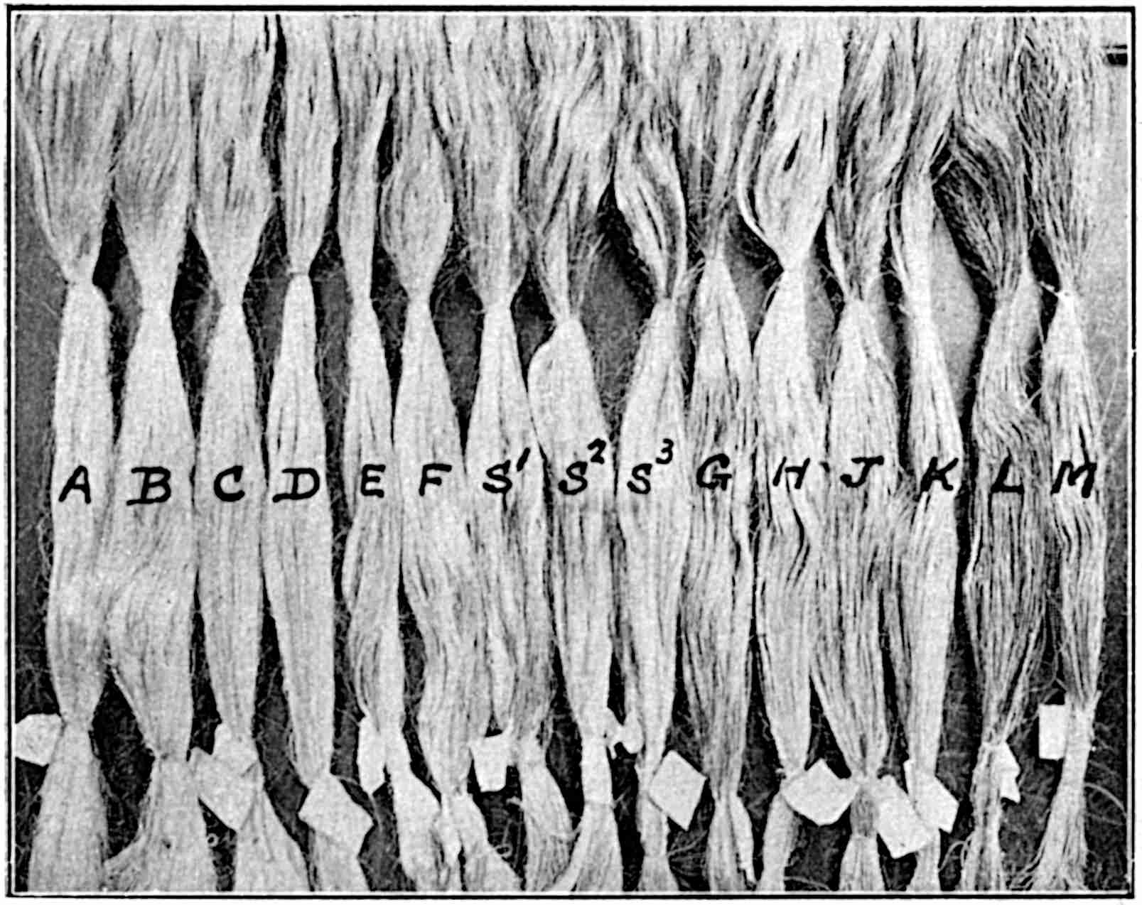
Another method of grading is by means of letters, and Fig. 10 is a photographical reproduction of fifteen different samples representing the general grading and marked A to M. There are also a few intermediate 35grades which are of similar classes of fibre but discoloured—a fault due to imperfect cleaning.
The imports of Manila to the United Kingdom for the years 1911 to 1915 inclusive and the actual value appear in the following table, while the average value of one grade, Fair Current, appears alongside. See also page 34.
| Year. | Tons. | Total Value. | Price per ton of Fair Current. |
|---|---|---|---|
| 1911 | 75,449 | £1,647,542 | £19 — — |
| 1912 | 83,313 | £1,990,481 | £21 10 — |
| 1913 | 64,579 | £1,600,450 | £34 — — |
| 1914 | 54,206 | £1,396,593 | £27 15 — |
| 1915 | 57,783 | £1,760,471 | £28 10 — |
Sisal.—This is a fibre which is almost of equal importance to Manila for the production of cordage. The plants, which are produced extensively in Mexico, Africa and the Bahama Islands, form a group termed the Agaves.
Those plants which are most extensively cultivated for fibre purposes have recently been classified, see page 8.
The particular Agave plant from which the Sisal fibre of commerce is obtained is the Agave Sisalana, or Henequen, natural order, Armaryllidaceae, the chief centres of production of which are Yucatan and Campeachy; the cities of Merida and Progresso are the centres of production of the fibre for the export markets.
The plants grow very successfully on waste and arid lands, and require very little attention after the preliminary operations of clearing the land and of planting out the young Agaves either as bulbules or “bulbils” produced from the creeping roots.
The stems of the plants are stumpy, and large fleshy 36leaves are produced which attain a height of 3 to 6 ft. The flowers are produced on a long stalk or pole which often rises to 30 ft. or more. The flowers appear in dense groups on lateral branches upon the axils of which develop bulbils; these grow to maturity and then drop to the ground where many of them take root and thus provide young shoots which may be replanted for another crop.
In the formation of new plantations for the production of fibrous plants, it is only necessary to clean the ground and dig the soil round where the young bulbils, suckers, or a mixture of both, are to be planted. They are so arranged that there is a greater space between the rows than there is between the plants in a row, say in the proportion of 8 to 6, and about 1,000 plants are spaced in an acre.
If the plants are taken from nurseries where the bulbils have been propagated for transplanting, it may be found advantageous to provide light tramways for their conveyance, as well as for the conveyance of the mature leaves in the opposite direction. The extra space between the rows is for facilitating such work by rails and other means. In fact, a plantation for the cultivation of Sisal plants and the production of the fibre should be laid out on a definite plan with provision, not only for successful cultivation, but for the subsequent operations of stripping, washing, cleaning and baling the fibre, while a desirable, if not absolutely necessary consideration, is the choice of ground in close proximity to a satisfactory district for labour.
A short time after the plants have been set it is advisable to clean and weed the ground periodically for at least two years to give the plants a favourable start; afterwards vigorous growth occurs, and no further attention in this line is necessary.
37It will be evident that a more vigorous growth will obtain in warm climates than in cold climates, but at the same time these warm climates may be exceptionally suitable; indeed, it has already been proved that, in some of the more recently-established centres of cultivation such as Africa, a better fibre is being produced than in some of the older established centres, and, moreover, the growing period is shorter.
To make a fibre-production area a success, it is advisable to adopt a systematic extension of the plantation each season, so that a continuous supply of leaves will be obtained, and that the available labour supply can be fully utilized either with operations in cultivation or fibre extraction; in this way a regular supply of fibre could be placed on the market for manufacturing purposes.
After a plantation is completed, the first cutting of the leaves may take place in from two to four years, depending upon the situation of the plant and its state. It is not necessary to cut down the whole plant; the larger leaves are cut when at maturity, and others as they mature; successive cuttings may be at intervals of approximately six months, after which the plant may be cut down and the spot allowed to remain fallow for a year, when a new plant is introduced.
The yield of fibre from the plants will vary considerably from time to time, such variation being influenced by the district, the weather and by the degree of perfection of the methods employed for extracting the fibre from the leaves.
The usefulness of the Agave fibres has been acknowledged for some time, and their value has been enhanced by the production of superior fibres in various centres of Africa as already stated; improved methods of cultivation and the use of modern and efficient stripping 38and cleaning machines may lead to the production of this type of fibre which will compete successfully with many of our most valued fibres for cordage use.
As the leaves are cut down from the plants, they should be removed at once to the stripping machine. The original name for such a machine was “Raspadore,” and supposed to be an invention of a Franciscan friar. The modern English word for the purpose is “Decorticator,” and, although the term “leaf-crusher” or “scutcher” appears to be more in keeping with the operation to be performed on Sisal leaves, than that of “decorticator,” a more extensive meaning has been given to the latter term which is now taken to indicate the mechanical operation for the separation of the pith and surrounding vegetable structure from the fibrous layers in practically every type of plant.
Two distinct machines, one for crushing the leaves, and the other for finishing the stripping, are made by Messrs. David Bridge & Co., Ltd., Castleton, Manchester, and these provide an excellent system for treating the leaves as they are delivered from the field of growth.
The crushing machine, termed Bridge’s “Acme” Gravity Patent Sisal Breaker, is illustrated in Fig. 11. The leaves of the plant are placed on the travelling endless cloth between the wooden side guides on the right-hand side of the illustration. They ultimately come into contact with the first pair of corrugated rollers which are so set that there is a minimum of ¼ in. between the surfaces of the opposing corrugations. After the leaves have been crushed between these rollers and carried forward by them, they pass between a second but smooth pair of rollers the nearest distance between the surfaces of which is 3/16 in. On emerging from these rollers, the leaves pass down the delivery table on the left. The upper roller in each pair is 40acted upon and pressed downwards by spiral or coil springs which not only yield slightly to the varying thicknesses of the leaves, but which will allow the roller to rise fully ⅞ of an inch in case any foreign substance should enter between the rollers.
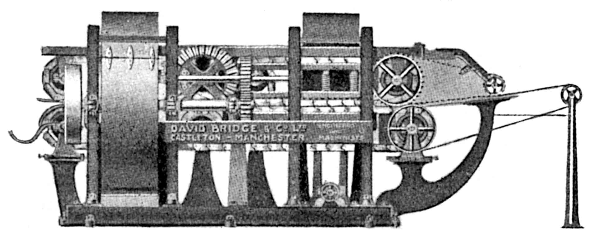
The crushed ribbons from the foregoing machine are now taken to Bridge’s “Climax” Patent Sisal Decorticator, illustrated in Fig. 12. As in the crushing machine, the material is fed into the rollers by an endless cloth; the ribbon-shaped lengths are exposed to the action of opposed drums on the same principle as that embodied in the original raspadore, the result being that the remains of the objectionable matter which accompanied the fibrous layer from the crushing machine is scraped off and a maximum amount of fibre delivered. The Decorticator is provided with all the latest improvements for a maximum production, and both machines, together with the washing tanks, Fig. 13, and the 43necessary power plant for driving the whole system can be housed in or near a simple structure somewhat as illustrated in Fig. 14.
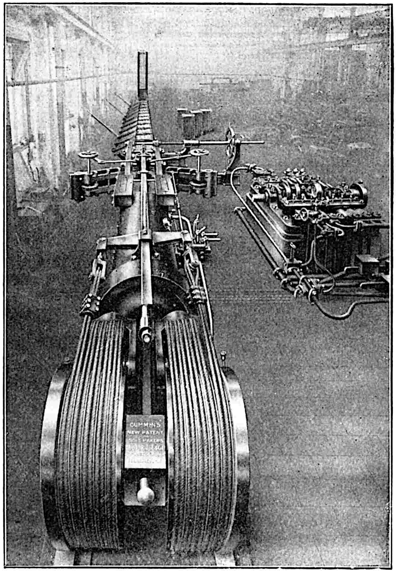
The fibre, having been extracted, washed and dried, is conveyed to the rapid baling press, Fig. 15, which is an illustration of Cummins’s Patent Horizontal Hydraulic 44Baling Press. Here the fibre is packed by hydraulic pressure into a small space ready for exportation to those countries where the fibre is to be manufactured. The above type of baling press is now largely used, not only for Sisal fibres, but also for China jute, cotton and other textiles, and it is capable of compressing the fibre to a density of 60 lb. per cubic foot.
After the third year’s growth, the annual production of fibre reaches about one ton per acre. The production of fibre from the various countries has been greatly increased during recent years, and that for 1914, which will be found in the table on page 52, may be taken as a good indication of the quantities placed on the market.
There has not yet been any considerable competition between Sisal and Manila fibres for the manufacture of similar types of cordage, but with improved methods of cultivation and of cleaning the Sisal product, a greater competition may be expected.
A large quantity of Manila fibre is used in this country for binder twine, whereas Sisal is used for the same purpose in the American centres. As a matter of fact, the U.S.A. markets of different kinds absorb 90 per cent. of the total Sisal crop which amounted in 1914 to 220,000 tons.
A new method of marketing the Sisal fibre from Yucatan has been introduced through a Committee or Commission who will be responsible for the grading and marketing of the fibre and will, with the sanction of the Government, deal entirely with the financial arrangements.
The Commission will receive all the graded fibre, and on receipt of this a payment will be made to the farmer. The fibre will be placed on the market at current rates, and every five years the accounts will be balanced and the surplus, if any, will be divided 45pro rata amongst the producers. In the case of loss, the deficit will be met by the Commission.
Sisal fibres are graded as under—
Special: perfectly clean and absolutely white fibre, free from stains or adherent pulp.
Superior Clean: perfectly clean fibre of creamy or yellowish tint, free from stain or pulp.
Current Clean: well scraped, whitish or greenish colour, 5 per cent. dust permitted. This is the standard grade for price.
Stained: also well scraped but with dark or red streaks. No more than 25 per cent. dark and no adherent pulp.
Inferior Stained: must be free from adherent pulp, but may contain as much as 75 per cent. of dark fibres.
New Zealand Hemp or Flax.—The botanical name of this plant is Phormium Tenax, natural order, Liliaceae. The plant has long, peculiarly-shaped leaves, the roots of which send out creeping rhizomes on which the leaves 6 to 10 ft. in height, are produced in clumps. Maturity is reached in about four years, and propagation is obtained by the growth of the rhizomes, and also by the self-sown seeds which are produced in large numbers from the flowering and fruiting stage.
Large quantities of this useful fibre are used, and it can be produced cheaply and in large quantities from otherwise unproductive lands, such as the drained swamp lands in the neighbourhood of the Manawatu river in New Zealand. In this district the plants grow in dense masses, and although more than 20,000 acres are under cultivation, additions are gradually taking place. Through this area are laid about fifty miles of light railway tracks. The plantations require little attention beyond that of careful drainage; over-drainage may cause as much damage as under-drainage. 46Wellington is the principal shipping port, but shipments are also made from Auckland and other ports when the value of the fibre makes such a course profitable.
Phormium Tenax has also been cultivated on a comparatively large scale in St. Helena, and the results, both financially and otherwise, are satisfactory. The selected lands in this island are now well drained, and tramways are laid for the rapid conveyance of the leaves after they are cut down to the stripping mills. Sometimes aerial railways are used when a river has to be negotiated. It will be quite well understood that a cheap and rapid transport is a desideratum.
Only well-matured leaves must be cut down, and these are conveyed to the stripping mills; in the Manawatu district of New Zealand about fifty such mills are in existence, and the introduction of improved machinery for this stripping operation will certainly lead to the extension of the cultivation of these plants and to the after processes.
Much has been done to introduce an efficient machine for stripping the leaves, and many premiums have been offered by the New Zealand Government for a perfect machine. One now under trial gives promise of good results.
The greatest difficulty in connection with the stripping of Phormium Tenax leaves is due to the peculiar shape of the lower end of the leaf. A very deep midrib extends for some distance and gets more pronounced as the lower end of the leaf is reached. A large quantity of the fibre is collected in this rib, the shape of which makes it difficult for mechanical parts to treat successfully, and necessitates a larger amount of labour than in the case of straight or flat leaves of the ordinary type.
In former methods of stripping and cleaning it was 47found necessary to paddock and bleach the stripped fibre, but the claims of the new invention, if sustained, will render these processes unnecessary.
The production of the fibre may reach 13 cwt., and 2½ cwt. of tow per acre during the life of the plants, while the stripper can produce from 20 to 25 cwt. of fibre per day.
The colour of the fibre is light yellow to brownish, but it is rather soft and dirty at the top end. It is graded as below—
| 91 | to | 100 | marks | = | Superfine, |
| 81 | to | 90 | „ | = | Fine, |
| 71 | to | 80 | „ | = | Good Fair, |
| 61 | to | 70 | „ | = | Fair, |
| 51 | to | 60 | „ | = | Common. |
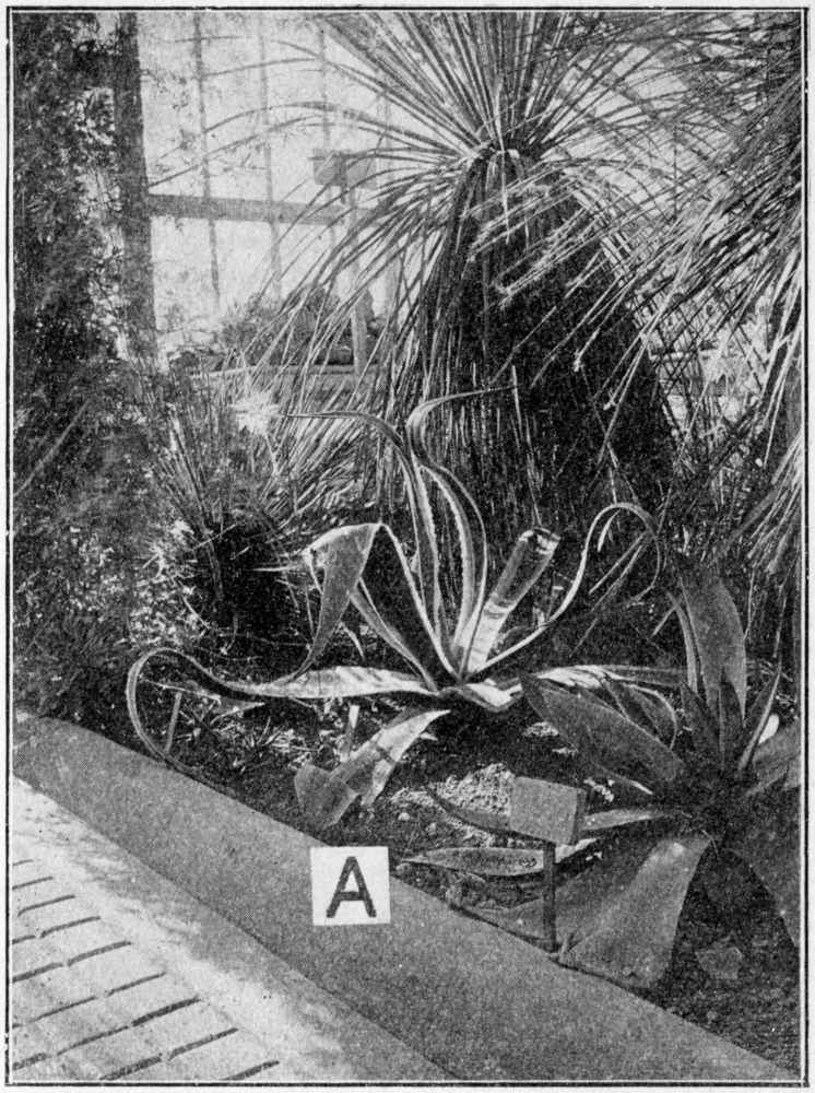
Other Fibres.—The chief hard fibres are augmented by the use of the “Maguey” plant which is cultivated largely in the Philippine Islands in districts bordering on the Manila centres, while Mauritius fibre is produced largely in the Islands from an Agave, the Furcroea Gigantea, order, Amaryllidaceae, known in Mauritius as “Aloes.” The plant, see Fig. 16, is somewhat similar to the Sisal plant, while the fibre obtained from it is of a soft nature, and is usually sent to this country in an imperfectly-cleaned state. The dust which accompanies the fibre emerges from it in the processes of manufacture, and is very disagreeable to the operatives. Owing, however, to its good light colour, and the softness and pliability of the goods made from it, the fibre is often preferred to the other hard fibres for certain types of work.
Coir.—Coir fibre is obtained from the husks of cocoa nuts. The extraction of the fibre from these nuts forms native industries in many parts of India and Ceylon. The husks are soaked in water for a time, and then 48beaten with sticks or mallets; the separated fibres are then dried and spun by hand with the aid of very simple appliances. Afterwards, two of these single yarns are combined or twisted together to make what is known as two-ply or two-fold twist. The twist is 49then made up into short lengths, rolled into small hanks and baled for export. Of later years, much longer lengths have been made and done up into coils, while small “dolls” or rolls are made up for sale in small quantities, particularly for use on farms.
Coir fibre has been very widely used for many purposes in the rope and cordage trade, principally for the manufacture of mooring ropes, spring ropes and lashing cords, while large quantities of the imported yarns are used for matting and farming purposes.
It is a very useful fibre when properly made up, and is of great importance for purposes where it is necessary for the manufactured article to be exposed to variation of climate and to wet, while the life of the manufactured article is greatly extended if it is steeped in oil.
Sunn Hemp (Bengal Hemp).—Sunn Hemp or Crotalaria Juncea, natural order, Leguminosae, is used on a smaller scale and for certain goods such as cheap grade ropes and box cord. The plants grow in several parts of India, e.g., near Bengal, Allahabad and Benares in which the cheaper grades are produced, and in some districts of Western Bengal where a better class of fibre is obtained. All are of the same family, the difference being due to the variation of the soil and the method of retting. (This is really a bast fibre, but it is used almost solely along with the hard fibres.) The fibre is harsh and very irregular in the lower grades; in the better grades it can be used to mix with other fibres for the production of tow yarns.
The other hemps obtained from India, particularly from Madras, are not so high grade as to warrant them being used alone to any great extent, so it is usual to mix them with other low-grade hemps of higher tensile strength, or these Indian hemps may be combined with scutching and hackling tows. The scutching and 50hackling tows are sometimes used to produce twines and cords suitable for box cords and for parcel tying yarns.
China Jute.—Although this is a bast fibre, its use is mostly confined to purposes for which the hard fibres are applied, and hence its introduction amongst them. It is a product of Hankow and Teintsin in China, and is largely imported to Great Britain. When suitably treated it forms a satisfactory fibre for the manufacture of box cords or similar goods where great tensile strength is not essential. The fibre is of a good light colour, and little or no waste is incurred in its transformation into cordage.
The following details of the production of fibres and relative costs are given so that the normal values, as well as the normal quantities may be judged, and also compared with the abnormal conditions which have prevailed during the great world’s war.
Italian and Naples hemp is imported to these islands in large quantities as will be seen from the following particulars for ten seasons—
| Season. | Italian. | Naples. | ||||
|---|---|---|---|---|---|---|
| 1903-04 | 62,000 | tons | 28,000 | tons | ||
| 1904-05 | 40,000 | „ | 23,000 | „ | ||
| 1905-06 | 12,000 | „ | 27,000 | „ | ||
| 1906-07 | 58,000 | „ | 30,000 | „ | ||
| 1907-08 | 58,000 | „ | 31,000 | „ | ||
| 1908-09 | 41,000 | „ | 20,000 | „ | ||
| 1909-10 | 55,000 | „ | 24,000 | „ | ||
| 1910-11 | 50,000 | „ | 27,000 | „ | ||
| 1911-12 | 33,000 | „ | 30,000 | „ | ||
| 1912-13 | 58,000 | „ | 31,000 | „ | ||
| 10) | 467,000 | 10) | 271,000 | |||
| 46,700 | average | 27,100 | average | |||
| Average | price | P.C. Italian, £39 11s. 3d. per ton |
|---|---|---|
| „ | „ | P.E. Naples, £41 9s. per ton |
| „ | „ | F.S.P.R.H. Russian, £31 17s. per ton |
51The prices since these dates have gradually increased, and the present prices are approximately as under—
| P.C., Italian | £190 | per | ton |
| P.E., Naples | £200 | „ | „ |
| F.S.P.R.H., Russian | £170 | „ | „ |
| China Hemp | £154 | „ | „ |
The following table illustrates the grading of Manila fibre for June, 1917, together with the number of bales for that month, and the percentage quantity of each grade. In addition, the last two columns give the prices; that for 1917 is the market price, while that for 1918 is the controlled price. Fig. 10 might be studied along with this table.
| Grade Letter. | Grade. | Bales. | % of Total. | 1917. Market Price per ton. | 1918. Market Price per ton. |
|---|---|---|---|---|---|
| A | Extra Prime | 899 | 0·7 | ||
| B | Prime | 2,182 | 1·6 | ||
| C | Superior Current | 6,852 | 5·0 | £150 | £155 |
| D | Good Current | 10,020 | 7·3 | £145 | £150 |
| E | Midway | 17,358 | 12·7 | £135 | £135 |
| S¹ | Streaky 1 | 1,865 | 1·4 | £130 | £130 |
| S² | Streaky 2 | 3,937 | 2·9 | £120 | £120 |
| S³ | Streaky 3 | 2,935 | 2·1 | £115 | £115 |
| F | Current | 22,284 | 16·3 | £125 | £130 |
| G | Seconds | 3,908 | 2·8 | £115 | £115 |
| H | Brown | 1,886 | 1·4 | £105 | £105 |
| I | Good Fair | 12,791 | 9·3 | £120 | |
| J | Fair | 13,561 | 9·8 | £85 | £100 |
| K | Medium | 4,226 | 3·1 | £80 | £95 |
| L | Coarse | 12,780 | 9·2 | £78 | £93 |
| M | Coarse Brown | 5,140 | 3·7 | £76 | £80 |
| DL | Coarse | 7,153 | 5·2 | £75 | £75 |
| DM | Coarse Brown | 4,306 | 3·2 | £73 | £73 |
| OYT | 3,159 | 2·3 | |||
| 137,242 | 100·0 |
52The standardizing of the grades has been rendered necessary by the large amount of inferior fibre which was being produced, and by the irregular baling of the fibre. The gradual improvement of the fibre as a whole may be gleaned from the undermentioned particulars of the number of bales which were graded into four of the lowest types. These numbers referred to what were allocated in August and September, 1917, and it will be seen that there was a much smaller percentage of these low marks in September than in August.
| Grade. | Bales: August. | Bales: September. |
|---|---|---|
| L | 10,548 | 7,462 |
| M | 4,553 | 3,201 |
| DL | 5,775 | 2,960 |
| DM | 2,290 | 952 |
| 23,166 | 14,575 |
The shipments of Manila and other fibres for six years, 1910 to 1915 inclusive, appear below—
| Year. | Manila bales. | Mexican Sisal bales. | New Zealand bales. | Mauritius bales. |
|---|---|---|---|---|
| 1910 | 1,272,000 | 582,142 | 103,750 | 9,990 |
| 1911 | 1,332,297 | 713,008 | 96,850 | 9,161 |
| 1912 | 1,466,110 | 859,000 | 96,360 | 8,697 |
| 1913 | 964,000 | 876,000 | 140,445 | 14,404 |
| 1914 | 943,000 | 982,000 | 98,510 | 8,947 |
| 1915 | 1,160,440 | 950,000 | 116,100 | 6,838 |
The three columns in the following table show the 54prices which ruled in 1915 and 1916 and the current prices for 1918.
| Type of Fibre. | 1915. | 1916. | 1918. |
|---|---|---|---|
| £ | £ | £ | |
| P.C. Italian Hemp | 55 | 90 | 190 |
| F.S.P.R.H. Russian Hemp | — | — | 170 |
| China Hemp | — | — | 154 |
| Manila (Fair) | 37 | 54 | 100 |
| New Zealand Hemp | 32 | 86 | 99 |
| Mexican Sisal | 28 | 77 | 97 |
| Java Sisal | — | 95-100 | 99 |
| Mauritius | — | 70 | 95 |
| Maguey | 30 | 70 | 74 |
The controlled Government price (U.S.A.) for Sisal fibre for June (1918) is as follows—
| 19 | cents | per | lb. | for fibre |
| 23 | „ | „ | „ | for 500 feet of binder twine |
Since one sheaf of corn requires about one yard of twine, and since the expected requirements for the Continent of America are 200,000 tons of binder twine, it follows that this weight of yarn will provide the binding material for 71,680,000,000 sheaves—almost an incredible quantity.
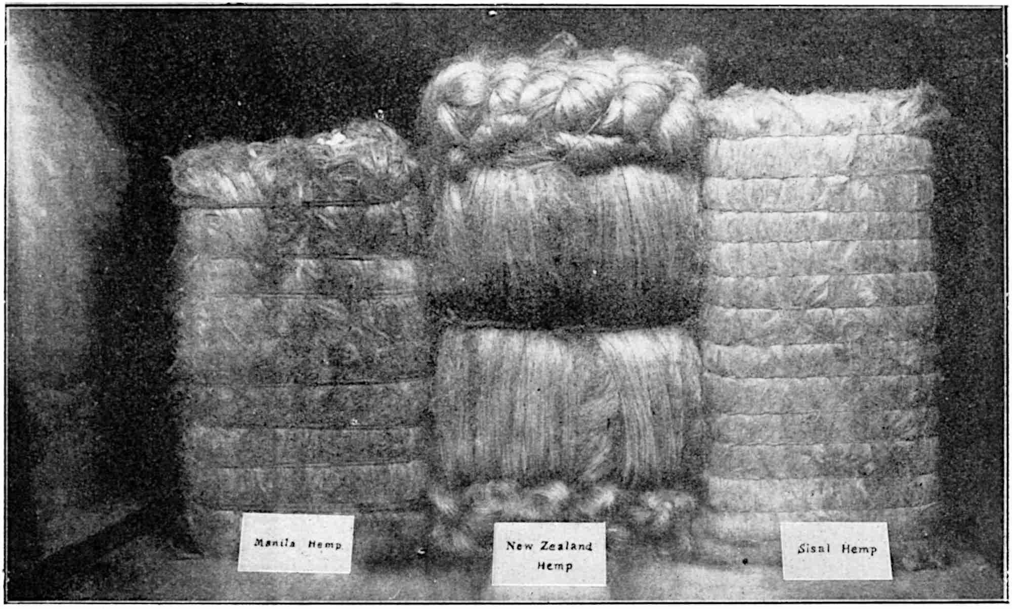
Fig. 17 shows three distinct methods of baling—
(a) Manila Hemp with rattan canes.
(b) New Zealand Hemp with ropes made from New Zealand fibre.
(c) Sisal Hemp with wire.
Since there is such a great variety of ropes, cords and twines, not only in regard to diameters, but also in regard to the different fibres used in the manufacture of these goods, it is not surprising to find that there are many different kinds of machines involved in the various operations; some of these machines are introduced for the special purpose of reducing the fibres to practicable lengths, but these machines are, of course, used only for the type of fibres which exceed about 36 in. On the other hand, it is sometimes found desirable to cut certain types of fibres which do not exceed the limits demanded by the capacity of the machines, but this is done only as a selective operation to obtain the best and strongest part of the fibre.
While certain classes of soft fibres such as Russian, French, Chinese and Indian hemps may be used without any previous hackling operation in the spinning of certain sizes of cordage, it is found that Italian, Serbian, Roumanian and Neapolitan hemps must be cut into suitable lengths and hackled before they can be passed through the preparing machines; in these latter machines the fibres are arranged into a practicable condition before they are subjected to the actual spinning operation.
The production of yarn for use in the making of cotton driving ropes involves the use of the whole system of cotton-spinning machinery, while, on the other hand, hemp yarns, besides being prepared mechanically, are 56still produced by a series of the simplest and oldest methods of hand hackling and hand spinning.
Fine ropes and twines may be, and often are, produced by an elaborate system of machinery, and modified forms of such a system, in which a smaller number of machines are employed, may be adopted for the spinning of the heavier yarns.
A complete plant for the manufacture of these yarns from soft fibres would include the following—
The yarns employed may be as small as 60’s for the finer sizes and as thick as 18’s for the heavy or common sizes; the significance of this yarn numbering will be explained later.
In order to have some definite purpose in view, let it be assumed that it is necessary to make a high-class rope from Italian hemp; the fibre to be used must, of course, be of a good quality of cordage hemp. When the bale of hemp is opened, the fibre will be found to be in “heads” or “stricks,” that is, collected into groups with a girth of from 8 to 12 in., and to be from 7 to 12 ft. in length and sometimes even longer.
The first operation is that known as “softening,” which makes the fibres, as the name of the operation indicates, more supple, and hence better adapted for undergoing the subsequent operations. Different makes of machines are in use for softening the fibrous material, the chief feature in each machine is that 57the heads or stricks of fibre are squeezed between fluted rollers.
In one type of machine the end of the strick is passed between the first pair of blades of an Archimedean screw, then between the fluted rollers of which there may be three, and its end brought round and joined to the other end of the strick; in this way an endless band of fibres is formed. The fluted rollers act as indicated, and at the same time the Archimedean screw gradually conveys the endless band of fibres from one end of the screw to the other end, each slight movement causing the fibres to enter between the fluted rollers at a different place. This type of machine, which is, however, rather dangerous for certain classes of workers, is considered quite efficient and satisfactory by many spinners, but the machine which is most extensively used is known as a “reciprocating softener,” and is made by such firms as Messrs. Reynolds and Messrs. Combe Barbour, both of Belfast, and by Messrs. Lawson of Leeds.
The action of the rollers of the reciprocating softener is rather complicated, for, in addition to the usual method of rotating in one direction for the sake of delivering the material, the rollers are moved bodily forwards and backwards a short distance alternately. The multiplicity of motions has for its aim that of subjecting every particle of the strick as much as necessary to the softening action of the flutes; the effect of these operations on the hemp is quite evident when the stricks emerge from the delivery end, for the material is much more pliant than when it entered, and is in such a condition that it may be greatly refined in the subsequent operations.
In this machine the forward motion of the rollers is obtained by a special arrangement of gearing from the pulley shaft which extends through the machine and 58carries a further belt pulley at the other end. A belt from the latter pulley drives by means of another pulley an upper shaft, while a further belt connection from a pulley on this upper shaft conveys motion to a pulley running on a stud projecting from the main frame. Compounded with the latter pulley is the speed change pinion, and a train of gearing, consisting of four pairs of compound wheels, conveys the desired motion to the fourteen pairs of fluted rollers which are arranged in two concentric semicircles in the upper part of the machine. The centre of these concentric semicircles is the central shaft of the machine, and on this shaft is placed the pinion and wheel of the second compound. Near the ends of this central shaft, and close to the outer part of the two main frames, swings two substantially-constructed brackets; each bracket has two horizontal arms from each of which a short shaft projects to carry a wheel and pinion, while the extreme lower end of the bracket is attached by means of a connecting rod to a crank placed on the large wheel below, and driven from, the main pulley shaft.
As indicated, this mechanism is duplicated, one set on each side of the machine. The object of the small pinions on the horizontal arms of the swinging brackets is to drive the fourteen pairs of fluted rollers through the medium of two large wheels, one on each side, each wheel being provided with internal teeth. The object of the cranks and connecting arms to the said brackets is to cause the fourteen pairs of rollers to reciprocate. This reciprocation adds to the effective softening of the stricks by rotating the material for a longer time in the machine, and thus repeating the softening effect of the rollers on different parts of the fibrous material.
After the stricks have been efficiently softened in one or other of the machines mentioned, they are conveyed 60to the cutting or breaking machine which is adapted to sever the stricks into lengths suitable for treatment in the hackling machine.
These cutting or breaking machines are of two distinct types—
(a) Those in which the fibres of the stricks are torn asunder; and
(b) Those in which the fibres are broken by the action of what are known as “cutting wheels.”
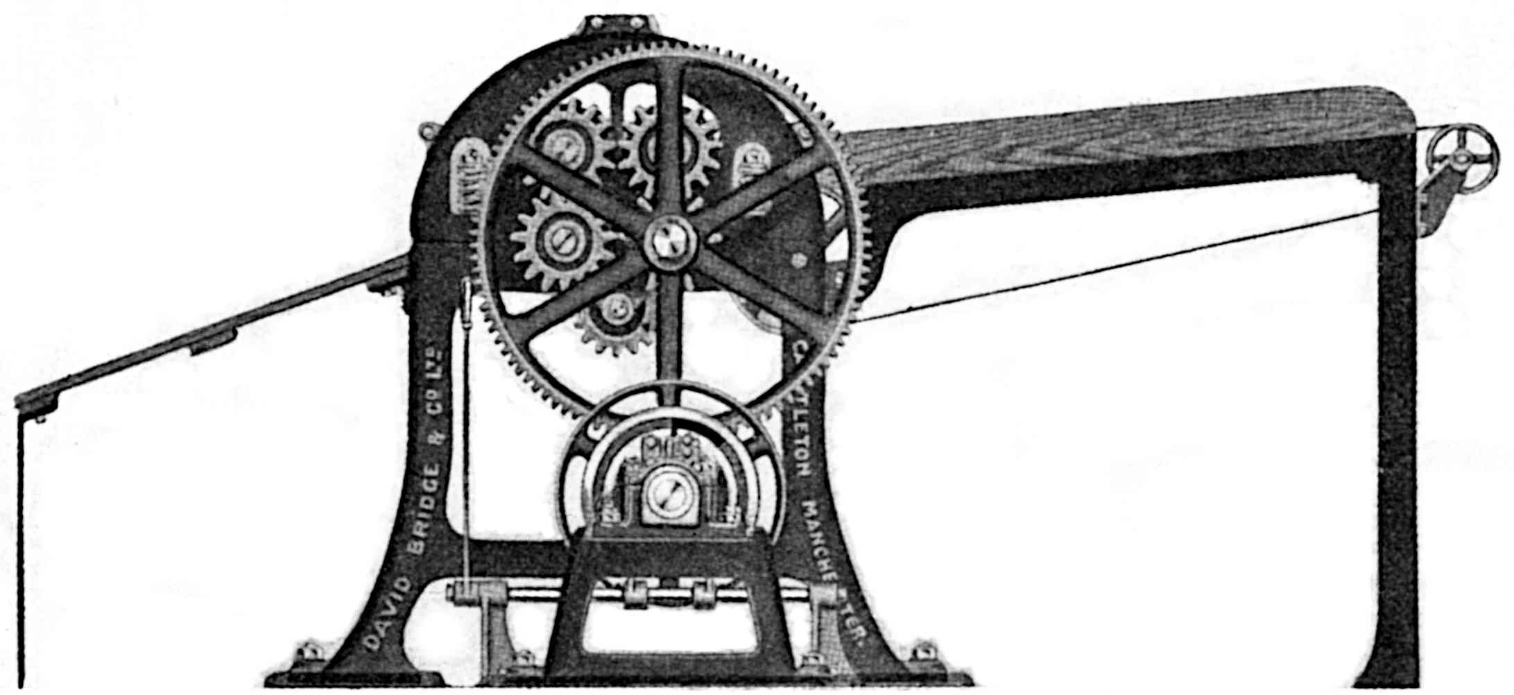
A good example of a machine which tears or breaks the stricks is that illustrated in Fig. 18, and made by Messrs. David Bridge & Co., Ltd., Castleton, Manchester. The machine is of substantial construction, but experienced operatives are required to take charge of it. One end of the softened strick is wrapped round the back fixed square bar to the left of the illustration; then about two turns of the strick are wrapped round the front square bar which rotates when the attendant presses down the foot lever near the floor. Since the revolving bar has a tendency to carry the strick round with it in virtue of the movement given to it by the train of wheels from the motive part, it follows that ultimately the stretch of fibres between the two square bars will be broken, and then the operation is repeated with the remainder of the long strick. The friction clutch, on the right of the three pulleys, and the main shaft are revolving continuously while the belt on the middle pulley is in motion, but the friction pulley itself moves only when the friction clutch is expanded due to the downward movement of the foot lever which, at the same time, releases the brake on the left pulley of the three. When the foot is removed from the foot lever or treadle, the clutch fork slides the clutch on the shaft and breaks the contact between the friction clutch and friction wheel; simultaneously the brake grips its 61pulley and thus arrests the wheels and the rotating square bar.
The cutting or breaking type is designed on quite different lines from the above machine, and a very popular and efficient machine of the former type is known as the “Revolving Cutting Machine.” A series of round pins (sometimes V-shaped teeth) project from the face or periphery of a large central revolving wheel, and on each side of this wheel, and at a suitable distance from it, is a pair of slowly-moving rollers which are grooved on their circumferences to intersect with each other and so grip or hold the material as it is being fed to the pins of the cutting wheel. The operative cutter stands in front of the machine with a long strick of hemp in his hands. He grips the strick at two convenient places, and, having decided upon the point where the piece should be cut or broken, he arranges for this point to pass into the machine midway between the two pairs of feed or retaining wheels. The machine is made in duplicate so that the same cutting, or breaking wheel may serve for both, but each operative has, naturally, his own set of feed wheels.
As already stated, the lengths of the pieces when broken or cut will depend upon the type of hackling machine in which the severed lengths are next to be treated, and also upon the particular class of rope into which the fibres are to be spun. The usual length limits are 24 in. and 30 in., although conditions might arise in which it is desirable to go beyond the extremes of these common lengths.
The suitable lengths of cut material are now made up into convenient sizes or bunches and conveyed to the machine hackling department.
Certain classes of Russian, French, Chinese, Indian and Italian hemps may be considered in common in all 62subsequent operations, and, in general, will require most of the treatment which is given to the specific case of Italian hemp under discussion.
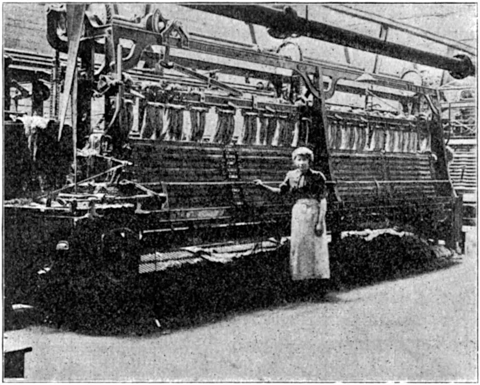
The hackling machines which are used in modern cordage or rope walks are similar to that reproduced in Fig. 19. In this particular machine there are sixteen different holders with pieces of hemp fibre depending from each, the lowest visible part of the fibre being on the same level as the uppermost part of the hackles or tools. The visible parts of the latter extend to a point in line with the waist of the attendant. There are four sections of tools in the full width, and each section is made up of four sets, while each set contains twenty-four tools, the whole arranged in a closed path so that while they rotate, the pins in the tools may act upon 63the pieces of hemp as the latter move in a vertical plane under the influence of what is termed the “head” of the machine.
The number of tools vary according to the accommodation available in the department devoted to this section of the work. The tools are fixed to a series of bars which in turn are riveted to a set of leather sheets, the whole being rotated as indicated by means of carriers which are arranged on two shafts with suitable fixings.
In the “head” the necessary mechanical parts are placed for moving the holders, and therefore the pieces of hemp, collectively and intermittently along what is known as the “channel.” The inclined rod, immediately under the name plate of the machine, with its additional parts convey this motion to each of the holders. In this manner, each holder, with its complement of hemp, is moved in regular succession opposite each of the sixteen sets of hackles or tools, and therefore passes from one end of the machine to the other. This movement takes place when the hemp is at or near its highest point. As each holder reaches the end of the machine, it is removed from the channel, the bolt of the holder unscrewed, the plate removed, and the piece of hemp turned end for end. After this the plate is again placed in position, the nuts screwed tight, and the holder entered into a similar channel on the other side of the machine, but with the undressed end of hemp downwards. A very similar movement is now imparted to the holders at this side of the machine so that the same process of hackling as that performed already may be imparted by an identical group of tools. The work is, of course, continuous in this respect that the girl or boy is almost constantly engaged with the attention of the holders as they reach the end in regular 64short periods of ten to fifteen seconds. The hemp ultimately reaches the end of the machine from which it started, but in a different plane, and is withdrawn from the holder to be replaced by an undressed piece.
Until a comparatively short time ago all the above operations of feeding were done by hand as explained, but most modern hackling machines have now attached automatic mechanism for performing these functions. The machine in Fig. 19 is provided with this automatic screwing and unscrewing mechanism. One attendant introduces the pieces of hemp between the plates of the holder when such plates have been separated by the apparatus, but from this point all the operations, including the removal of the holder, the turning of the piece of hemp, the unscrewing and screwing of the nuts, and the insertion of the holder with the unhackled ends downwards into the second channel, are performed by this ingenious group of automatic machinery. The design of such machinery differs with different machine makers, but very similar principles are embodied in all. The ends of the hackling machine frame are in all cases substantially made so that all parts may give the minimum amount of trouble in actual work.
The size of the pieces which are held by the holder and acted upon by the tools during the operation of hackling will depend upon the class of yarn to which the fibre has to be spun. As a general rule, the pieces for rope and twine yarns are arranged so that there are two to four per pound; in other words, the pieces are from ¼ lb. to ½ lb. each. It must be remembered that the finer the quality of yarn desired, the more hackling must take place, and hence it will be necessary to use a hackling machine with finer tools, and also to employ more tools in a row.
As a general rule the best yield of fibre is obtained 65when the maximum number of tools are used, but at the same time it is necessary that the grading of the pins or hackles in such tools should be judiciously chosen in order that the splitting or cutting should be gradual, and thus exercise a less violent action on the fibre than would obtain with an indifferent grading.
In addition to the grading of the pins, advantage may also be taken of what is known as the “grouping,” that is, the order in which the pins are arranged on the tools. The grouping is of the greatest value in the coarser-pitched tools, and although some hackling experts prefer to have the pins in two rows on the finest tools, the Authors consider that when all the pins in the finer tools are in one row, the work is done better for the line, and the tow produced is of good quality, while such an arrangement offers the best and most economical facilities for keeping the tools in good condition. A good arrangement of grading and grouping on ten tools may give a greater variation in the splitting or cutting than would result from an indifferent arrangement of grading and grouping on a larger number of tools.
Three different arrangements of grading appear below—
| Number of pins per inch width of tool | |||||||||||||||||||
|---|---|---|---|---|---|---|---|---|---|---|---|---|---|---|---|---|---|---|---|
| ¼ | ½ | ¾ | 1 | 1½ | 2 | 4 | 6 | 8 | 10 | = | 10 | tools | |||||||
| ⅛ | ¼ | 1/3 | ½ | 2/3 | 1 | 1½ | 2 | 3 | 4 | 5 | 6 | 8 | 10 | = | 14 | „ | |||
| ⅛ | 1/6 | ¼ | 1/3 | ½ | 2/3 | 1 | 1½ | 2 | 3 | 4 | 5 | 6 | 7 | 8 | 10 | = | 16 | „ | |
All modern hackling machines should be arranged to give the best possible yield of line, and also of tow, from the material which is in process, since by this effort an increase in the relative value of the finished article is obtained, and a highly-valued product secured at a comparatively low cost of manufacture.
As the pieces of hackled hemp are delivered from the 66hackling machine, they are made up into suitably-sized bundles and conveyed to the line store.
A record of all the materials in the various stages of manufacture is kept in the books of the respective departments, and such records can quickly be referred to at any time by those who are responsible for the production of the various classes of goods which are being made.
As already indicated, certain classes of hemp may be so clean when purchased, that they can be used for some types of cordage yarns without any preliminary hackling, and goods made in this way may compete favourably with those made by processes which include hackling. The object aimed at in these cases is usually one of price and not exactly of quality, for when the latter is the predominating condition, the superior value is attached to the yarns made from hackled fibre. Nevertheless, when it is simply a question of equivalent suitability for specific purposes, and when approximate values are obtainable by the two methods of manufacture, the conditions offer a choice which is of extreme importance at those times when the available suitable fibre for either method is scarce, or when either is very abundant.
Although the above choice presents itself for the cases mentioned, it will be understood that for the better grades of cordage one must employ either a very high grade of cleaned hemp, or a grade of hemp which has been hackled and cleaned by hand or by suitable kinds of machines.
In very special cases, e.g., high-class threads and cord yarns, where great strength and uniformity are desired, it has been found advisable to prepare the fibre entirely by a system of “hand dressing.” The hand method lends itself naturally to more careful selective 67treatment. It should, however, be stated that it is not usual to adopt this method except for the production of a comparatively small quantity of fine yarns, that is, thin yarns. Sewing twines and cords should be level and strong, but not necessarily fine, unless for the finest class of work into which these threads are to be introduced, as, for example, in the glove industry in which case the fibre used is often flax. These finer grades of threads and twines, as well as the finer classes of cordage, may require the whole range of operations to produce the finest and cleanest product consistent with the work for which it is intended to be used, although, as stated, the hand hackling may be employed for the flax intended for use in the manufacture of fine thin yarns, whereas, it is preferable to employ machine hackling for the equally valuable but thicker yarns. From this stage, however, the operations for the continuation of the processes of manufacture from the two distinct types of dressed line are conducted mechanically.
In perhaps the most extensive scheme of hackling there is a combination of hand and machine work. The first operation is termed “Roughing,” and consists of drawing the pieces of hemp or flax through a set of hackle pins arranged or grouped in a wooden block, and termed a “Rougher’s Tool.” This operation, when correctly performed, leaves the fibres practically parallel, their ends approximately in line with each other, and separates these long fibres from the shorter ones which are left amongst the hackle pins, and which are removed regularly to be ultimately used as “tow” in what is known as the “carding” process. These long, partially-combed and split fibres are now taken to the hackling machine to undergo a further treatment of combing and splitting as already briefly described. Finally, when the pieces leave the hackling 68machine they have to undergo for a second time a hand process of hackling which is termed “Sorting and Selecting,” after which the material is made up into a bundle.
It is obvious that such an extensive scheme of hackling is not only slow but also costly, and is attempted only for the most valuable raw materials to be used for costly finished goods such as fishing lines, fine cords, and for valuable threads which are used in the glove, leather and cognate industries.
It will thus be seen that there are in reality three distinct methods of preparing the fibres into the product known as “line,” and the finished product thus obtained then passes through a series of machines, termed a “system,” in which the fibres are first arranged in such a way as to form a continuous thin and broad ribbon termed a “sliver,” then into a more or less circular and slightly-twisted form termed a “rove,” and ultimately into a much finer circular and twisted form termed a “yarn” or “single thread.” Rope and heavy cordage yarns are often made by a simpler process than that just enumerated. The operations which these yarns or single threads subsequently undergo will be discussed at the proper place. In the meantime we purpose mentioning the different machines, and then briefly to describe and illustrate these machines which jointly form what we have called a “system.”
| System I for Fine Classes of Line Yarn. | System II for Heavier Line Yarns. | System III for Common Yarns from Tow. |
|---|---|---|
| Spread Board | Spread Board | Carding Machine |
| Sett Frame | Sett Frame | Drawing Frames |
| Drawing Frame | Finishing Drawing Frame | Roving Frame |
| Roving and Gill Spinning | Automatic Spinning | Dry Spinning or Automatic Spinning |
| Dry Spinning |
69The machine known as the “spread-board” is so called because the function which it performs is the mechanical sequel to the manual operation which was conducted somewhat as follows: A board about 9 ft. long was covered with an even layer of the pieces of hackled flax or hemp so arranged that each succeeding piece partially overlapped the one immediately before it much in the same way, so far as overlapping is concerned, as obtains with the scales of a fish or the parts of a fir cone. One operative would place his hands on the material thus arranged, while another operative would draw forward the material, reducing it in girth but increasing it in length, by causing some of the fibres, and all of them in turn, to slide a distance on their neighbouring fibres. At the same time the drawn-out material would be kept as uniform as possible in thickness, and the operation would be continued until the thin drawn-out length was probably five to ten times the length of the more bulky material which was originally laid as explained on the board.
The modern technical term for this elongation or attenuation of groups of fibres is “drafting,” and the dual operation described above is now performed in the modern spread-board, the delivery end of one of which is illustrated in Fig. 20.
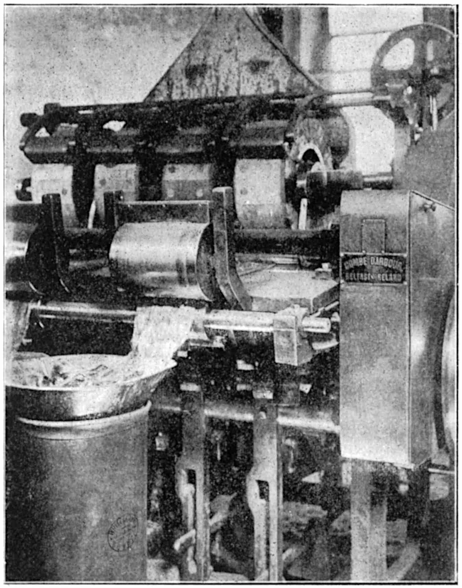
The use of the spread-board is rendered necessary because the pieces of material from the hackling machine are made up of individual and comparatively short lengths of fibre, and the essential object for the satisfactory continuation of the processes of manufacture is to convert these short lengths into a continuous length termed a “sliver.”
The pieces of hemp or the like are first weighed in a balance near the feed end of the machine, and are then arranged by hand on narrow endless travelling belts, 70termed “spread leathers,” so that the thin end of one piece of hemp is overlapped by the thick end of the next piece and so on. These “spread leathers” form the moving bases of narrow channels, the sides of which keep the pieces of hemp in their own channel. But instead of only one row of moving fibres or pieces as in the primitive process, there may be four or six of the above-mentioned channels.
71The neatly-arranged pieces in each channel are carried forward slowly but continuously, each group by its own endless belt, until all the groups reach the first pair of rollers called the back or retaining rollers. After the pieces leave these rollers they are penetrated by a large number of pins or hackles arranged on what are known as “gills” or “fallers.” There may be four or six gills on each faller, and the fallers rise in turn to cause the pins to enter the narrow sheets of fibres, to join the faller which immediately preceded it, and to move along with the majority of the fallers in a body towards the drawing rollers. In the spread-board illustrated in Fig. 20 there are four channels, and therefore four pressing rollers in contact with the drawing roller which extends the full width of the machine; all the four pressing rollers are distinctly shown near the upper part of the illustration.
It will be understood that the four narrow sheets of fibres will ultimately reach the drawing and pressing rollers, and since the surface speed of these rollers is much greater than that of the back or retaining rollers, the fibres which are clear of the grip of the retaining rollers will slide on those whose movements are restrained by the rollers and gill pins, and since there is always a quantity thus liberated, the draft is accomplished according to the relative speeds of the two sets of rollers. The effective contact between the rollers for drafting is obtained by means of levers two of which are shown near the floor and to the right of the sliver can in Fig. 20.
The gills or fallers are moved forward by spirals or screws and at practically the same surface speed as the “spread leathers” and the retaining rollers; as each faller reaches its full forward position, it is caused to move downward and then backward in a lower plane, 72and ultimately to rise again to enable the pins to enter into a fresh portion of the sheet of fibres; after this cycle is completed, the same functions are repeated while the machine remains in motion.
The four slivers which leave the drawing and pressing rollers unite into two pairs through the medium of doubling plates; one pair of slivers thus united is guided to a conductor, and then passes between the delivery rollers and into a sliver can shown in the foreground of Fig. 20, while the other pair, part only of which appears in the illustration, follows a similar course into a neighbouring sliver can.
The extent to which the fibres are drawn out in the spread-board, that is, the draft of the material, varies from about ten to twenty.
The gradual tendency to call into action mechanical parts to perform work which was originally done by hand is further emphasized in the latest attempt to feed the above-mentioned short pieces of hemp or the like automatically from the hackling machine to the spread-board. This ingenious device, the invention of Mr. Joshua Eves, of Belfast, carries the hackled pieces from the holders of the hackling machine and lays them on the “spread leather” in the channel, and, in addition, it is provided with a regulating device to preserve as near as possible uniformity in the thickness of the resulting sliver which, as usual, is delivered into sliver cans as already described.
Even with the greatest care, the most efficient type of machine and the finest stage of hackled fibre, it is practically impossible to achieve an absolutely uniform sliver. In order, therefore, to approach a practicable ideal sliver, it is usual to resort to a process of “doubling” and a further operation of drawing; indeed, the next machine to which the slivers pass is termed a 73“drawing frame.” Before dealing with this machine, however, it is desirable to discuss another distinct method of forming the initial sliver from fibrous material.
In general, the sliver prepared by the spread-board is intended for the production of level and high quality yarns, but it is evident that, during the operations of scutching and hackling, a certain quantity of the shorter fibres will become detached from the main body of the strick. These shorter fibres, termed tow, are not only weaker than the line fibres but are also accompanied by impurities which must be removed in the subsequent operations; they are graded according to quality, and ultimately treated by a distinct method which, however, prepares them into a sliver very similar to that which emerges from the delivery rollers of the above-described spread-board. Then, as already mentioned, the after processes for both types of sliver are practically identical.
The conversion of this tow into a sliver takes place in what is known as a “carding” machine. This is a particular construction of a general type of machine which is used for the same purpose in most textile trades where comparatively short fibres have to be converted into sliver form.
The function which the card—a contraction for carding machine—performs is to split up the fibres and to lay them parallel with their neighbours; for this purpose the machine is provided with a series of rollers which are covered or clothed with sharp pointed pins, the size, direction and inclination of which depend upon the particular work which each set has to perform. A set of cards comprises two or more machines each of which differs slightly from the others, and invariably arranged so that succeeding machines in a set are provided with finer clothing, i.e., smaller and shorter pins and more closely set. The simplest set is where two 74machines are involved, the first one termed a “Breaker Card,” and the second one termed a “Finisher Card.” In both machines a series of comparatively small rollers, say from 8 to 20 in. diameter, and covered with pins, are arranged partially round and close to a large central roller of 4 to 5 ft. diameter, also covered with pins and termed a cylinder. The general appearance of the machines will be gathered from the two rows in Fig. 21; the nearest machine on the left shows the delivery side of a breaker card where the sliver is delivered into a can; the nearest machine on the right illustrates both feed and delivery sides of a finisher card.
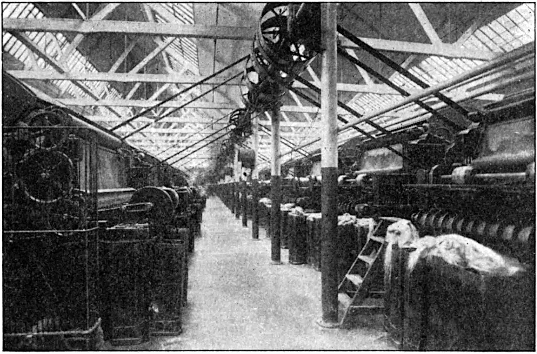
The tow, which has been previously softened, is laid as evenly as possible on a travelling endless sheet by means of which the fibrous material is carried to the pins of the “feed roller” which rotates very slowly 75and at the same surface speed as the feed sheet. Immediately the material emerges from the feed rollers, or feed roller and “shell,” it is acted upon by a series of hackle pins projecting from the periphery of the cylinder, and moving at a surface speed of more than 2,000 ft. per minute. The fibres are therefore combed and carried off the pins of the feed roller by the pins of the cylinder to a series of rollers arranged in pairs, each pair consisting of a “worker” and a “stripper.” When the fibres on the pins of the cylinder reach the first pair of worker and stripper, the bulk of the material is carded and ultimately returned to the pins of the cylinder to be carried to the next pair of rollers, and so on, until it has been sufficiently equalized and cleaned for the particular yarn into which it is to be made.
By this time the uneven fibres have been considerably reduced in thickness, and have indeed been converted into a thin wide film or sheet of fibrous material, and in this state it is removed from the pins of the cylinder by the pins of a “doffing roller” or “doffer.” The thin, broad film of fibres now enters between a pair of drawing rollers—seen near the top of the machine on the left in Fig. 21—and into the upper and wide part of an almost vertical tin conductor. The width of this conductor decreases from the upper to the lower end, and ultimately its width is contracted to about 3 in. where the contracted sheet, now much thicker and about 3 in. wide, is in the well-known form of a sliver. The sliver emerges from the mouth of the conductor, enters between the delivery rollers and ultimately drops into a sliver can in a very similar manner to that depicted in Fig. 20.
About ten or twelve of these sliver cans from the breaker card are now transferred across the space, termed a “pass,” to the feed of the finisher card on the 76right of Fig. 21. These ten or twelve slivers are fed into this machine and they undergo a further and similar treatment with from four to six pairs of rollers, and finally the finished and single sliver is delivered into a can near the side of the machine. In both machines the material is drafted according to requirements.[1]
We have thus arrived by two several ways at the production of a continuous sliver. Both types of sliver pass next to what is known as a “Drawing Frame,” or rather to a set of drawing frames, usually termed, first drawing, second drawing, third drawing, and so on, if more than three are employed.
The machines used for the two kinds of slivers are practically identical in principle and construction, the only difference being that provision is made to suit the lengths of fibres of which the respective slivers are formed; in technical phraseology the “reach” for the line sliver is longer than the “reach” for the tow sliver and is, approximately, proportional to the maximum length of fibres which compose the two types of sliver.
It will be understood that, in general, the ultimate aim is the production of a thread of some kind, the sectional area of which is less than that of the sliver which is produced either at the spread-board or the finisher card. And it will be obvious that if we unite two or more slivers at the feed side of the “Drawing Frame” we increase the thickness or volume proportionately; hence, if the sliver which is delivered from the drawing frame is required to be smaller in volume than any of the single slivers which enter the machine, and this is generally the case, although not universally 77so, the process of drawing out the fibres, or drafting, must be continued. In the first drawing frame uniformity is chiefly the object, and it may happen that in the combined processes of doubling and drafting it may be convenient to produce in this frame a sliver of greater volume than the individual slivers at the feed. In such cases, most of the drafting would take place in the succeeding drawing frames.
The first drawing frame is often termed a “Sett Frame,” and sometimes a “Doubling Frame.” The first-named of the three owes its designation to the process of attenuation or drafting, the second to the number of slivers which in the process are employed to form one sliver, and the third to the particular case where two slivers only are united. Although the exact meaning of doubling is the combination of two slivers, the same word is used however many slivers are combined in one group.
The drawing frame has a great resemblance to the spread-board, so far as the principles of the operations are concerned; it differs from it in the fact that whereas the latter is fed by short detached lengths, the former is fed by continuous slivers.
The length of sliver which is delivered from the spread-board is measured; this is accomplished by the size of one of the drawing rollers and the necessary subsequent mechanism; these jointly cause a bell to ring, or to move a hand over the face of a clock. The length thus indicated is called the “bell or clock length,” and whichever system is adopted, the operative receives a certain weight of material which must be fed into the machine between two consecutive ringings of the bell, or during the time that the clock hand makes one complete revolution.
The cans are weighed as they are filled and the net 78weight of the sliver marked on. After a sufficient number of cans have been filled, say eight, averaging 20 lb. each, or 160 lb. in all, and the length of sliver in each can, say 250 yd., eight cans are placed at the feed side of the drawing frame. The average weight of the combined slivers on entering the drawing frame is, therefore—
| 160 lb. × 16 oz. per lb. | = approximately 10 oz. per yd. |
| 250 yd. length |
If the draft is, say 12, the 160 lb. of material when delivered in the form of a single sliver will be—
250 yards × 12 draft = 3,000 yd.
Then—
| 160 lb. × 16 oz. per lb. | = 0·85 of an ounce per yd. |
| 3,000 yd. of sliver |
The operation of drawing is conducted as in the spread-board by means of retaining or back rollers, gills, drawing and pressing rollers. It should be again pointed out that the distance between the retaining rollers and the drawing rollers—termed the “reach”—should be regulated by the length of the fibres under treatment, and should be greater than the longest individual fibres, otherwise such fibres, instead of sliding on those already held, would obviously be broken because the surface speed of the drawing rollers is much greater than that of the retaining rollers; in the case under notice the ratio is 12 to 1.
The best scheme yet devised for filling up this intervening space between the two pairs of rollers, and of providing support for the moving fibres is that of the above-mentioned gills. The use of gills in the machine is of great importance, for on the correct adaptation of the gills to the material in process depends the degree of efficiency of the machine.
79As the gills move from the retaining rollers towards the drawing rollers in virtue of the action of suitable spiral or other mechanism, each group forms a compact sheet or field of hackle pins, and this field of pins regulates and restrains the movements of the fibres to the requisite extent as the latter move amongst them due to the pulling action of the drawing rollers.
In this way each individual sliver in its own set of pins is reduced in size, and any local defect in a sliver is calculated to be overshadowed or eliminated when the said sliver joins the remainder of the slivers at the “doubling plates” which are situated between the drawing and the delivery rollers. The result is, therefore, a single sliver of greater uniformity than any of the constituent slivers, such sliver being smaller, equal to, or greater than, any of the individual slivers from which it has been made according to the ratio of the doublings and draft.
A series of drawing frames in system as illustrated in Fig. 22, will provide the necessary doubling and drafting, and so reduce the sliver to a suitable size for use in any of the following yarn-forming or spinning machines—
(a) The Roving Frame which would be used to convert the sliver into a somewhat circular form, and simultaneously to wind this twisted sliver on to a large two-ended bobbin ready for the spinning frame (dry spinning).
(b) The Gill Spinning Frame which is a machine by means of which very high-class yarns can be produced with a perfect system of drafting and twisting in one operation.
(c) The Automatic Spinning Frame in which the heaviest class of cordage yarn is spun by the simplest and most direct method.
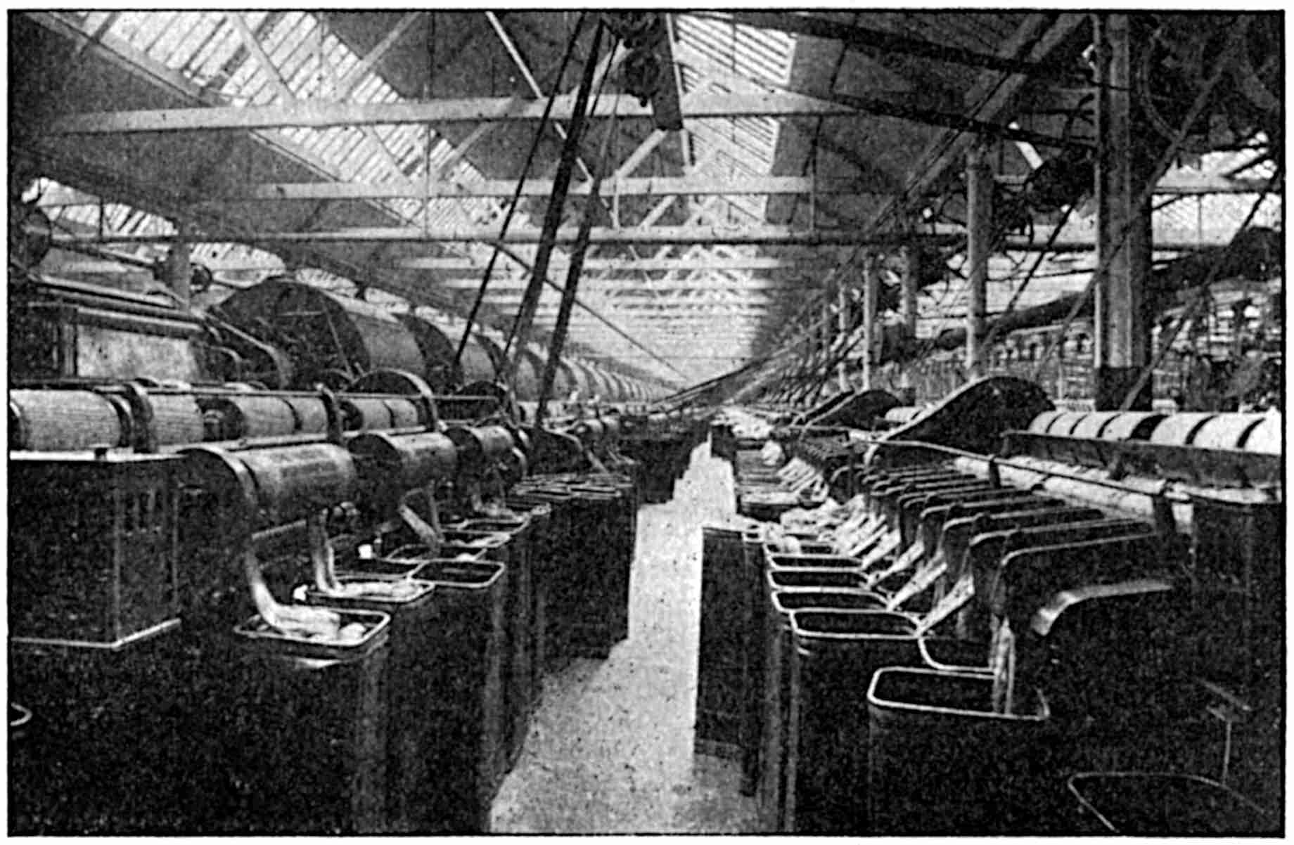
The roving frame is one of the most complicated groups of mechanism and one of the most perfect machines which is used in the whole system. Its function is of a multiple type, for the mechanism of the machine not only necessitates the use of retaining rollers, gills and drawing rollers to effect a draft, but after the reduced sliver has been passed through the delivery rollers, it introduces a certain amount of twist to the sliver—incidentally making it somewhat circular in section—and finally winds the twisted sliver, termed “rove,” on to a large bobbin.
The method of drafting has already been briefly
described, hence, no recapitulation is necessary. The
essential amount of twist for each individual sliver is
imparted by its own spindle, an upright rod which
81rotates rapidly, and upon which the large bobbin runs
or rotates loosely, while attached to the top of the
spindle is a “flyer” resembling an elongated inverted
U, thus:  . Most of these parts are clearly seen in
Fig. 23, which represents, of course, the delivery side
of the machine. At the other side of the machine,
the feed side, there is a sliver can with its sliver for
each thread and bobbin, the bobbins being arranged
in two rows upon discs in corresponding holes in the
long shelf, termed the “lifting rail,” the “builder rail,”
or simply the “builder.”
. Most of these parts are clearly seen in
Fig. 23, which represents, of course, the delivery side
of the machine. At the other side of the machine,
the feed side, there is a sliver can with its sliver for
each thread and bobbin, the bobbins being arranged
in two rows upon discs in corresponding holes in the
long shelf, termed the “lifting rail,” the “builder rail,”
or simply the “builder.”
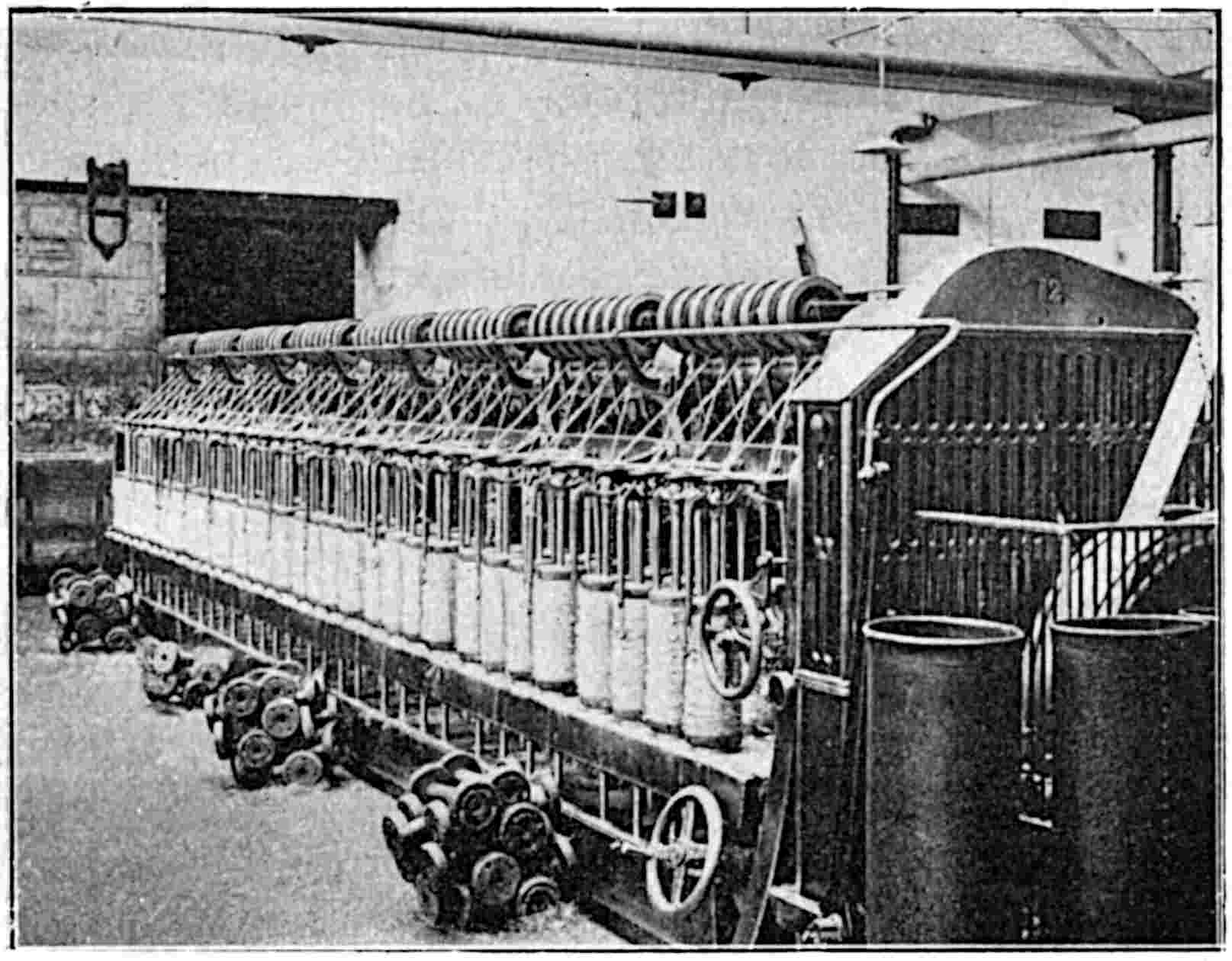
The extreme ends of the two legs of the flyer are bent to form or carry eyes, and into one of these eyes the twisted sliver is passed, while between this eye and the delivery rollers the sliver is centralized by passing it 82through a guide eye. The function of the eye in the flyer is that of guiding or winding the rove on to the bobbin, and this is made possible because the bobbin itself is made to rise and fall between the legs of the flyer through a distance equal to the length of the bobbin—hence the necessity for the long legs of the flyer or inverted U.
The spindles and bobbins are driven independently and positively by wheel gearing, and it is obvious that the rove must be wound on to the bobbin at the same rate as it is produced. Since the speed of the drawing and delivery rollers is constant, the delivery of the sliver is constant, and so is the production of rove, although the length of rove delivered is infinitesimally less than that of the sliver in virtue of the small contraction which takes place during the twisting. If the diameter of the rove on the bobbin always remained the same size, which is obviously impossible, the revolutions of the bobbin would be constant. But every layer of rove which is wound on to the bobbin by the joint action of the rotating spindle, the rotating bobbin, and the vertical movement of the bobbin on the builder, adds for each vertical movement, up or down, one more layer of rove to the partially-filled or empty bobbin, and thus increases the diameter of the combined bobbin and rove. Hence it is necessary to impart what may be termed an intermittent and variable motion to the bobbin; this is done by an exceptionally unique and intricate group of mechanical parts termed the “differential motion.” The function of the differential motion is to alter the speed of the bobbin after each complete layer of rove has been wound on to it, because it will be clear that when the direction of the builder is changed, the winding of the rove is performed on a diameter which is greater than the last by approximately twice the diameter of the rove. The discs 83upon which the bobbins rest are provided with two vertical pins which enter two of the holes in the flange of the bobbin, seen clearly in the empty bobbins near the frame, and by means of which the bobbins are driven at the desired speed. Accurate adjustment of the parts is necessary, and a lengthy description with numerous line drawings are essential to a clear understanding of this ingenious mechanism.[2]
Spinning.—The bobbins filled with rove yarn, as illustrated in Fig. 23, are ready to be removed or “doffed,” as the operation is technically called, preparatory to being taken to some type of spinning frame where a further extension or “draft” of the yarn takes place, and simultaneously the finished product of the desired thickness or “count” is wound upon a much smaller two-ended bobbin.
A large-used type of dry spinning frame is illustrated in Fig. 24, and this type of machine is usually employed for spinning yarns the “counts” or “sizes” of which are represented by the numerals 3 to 16. Yarns which happen to be of lower or higher count than these limits are produced on other similar or different type of machine.
In Fig. 24 the large rove bobbins are seen distinctly on projecting pins—termed a creel—at the top of the machine. Each rove from its bobbin, which can rotate freely on its peg, is passed between retaining rollers, and over what is known as a “breast-plate,” through the contracted groove of a “tin conductor,” between a pair of drawing rollers, through a slot in the 84“thread-plate,” through an eye in one of the legs of the flyer, and ultimately on to the bobbin which rotates on a spindle upon the upper end of which the flyer is fixed. In “long-reach” machines it may be necessary to use additional rods or binders which act as auxiliary breast-plates.

All the spindles on one side of the frame are individually driven by flat tapes or round bands from a driving tin cylinder situated near the floor and inside the frame as shown in Fig. 24, and driven direct from the main pulley. The flat tape or band passes partially round this cylinder, and then partially around a “whorl” 85or bobbin-shaped pulley of about 1½ to 3 in. diameter on the spindle; these whorls and tapes are seen clearly on the first three spindles in the illustration, and in the same line as the “temper weights.” The latter hang from cords attached to the back of the “builder” which imparts the up and down motion to the bobbins during the operation of spinning, and so enables the yarns to be distributed over the full length of the bobbin. The cord which is attached to the temper weight is caused to bear on the grooved flange of the bobbin, and by moving the cord into successive grooves or notches in front of the builder as the bobbin fills, a greater part of the groove is acted upon by the cord and weight, and thus the drag is increased.
Demi-sec spinning, as the name implies, refers to a process between dry spinning and wet spinning. In the demi-sec frames a slight quantity of water is added to the drawn-out and partially-twisted threads as the latter pass from the drawing rollers to the flyers. The purpose of this moisture is to smooth and lay the hairs of fibre which would otherwise project from the main body of the yarn as in the case of dry-spun yarns. It is usual to apply this method of spinning to thread yarns.
The draft necessary for converting the rove to the desired size or count of yarn is regulated by changing the value of the gearing, the wheels of which are enclosed in the oval covering at the end of the view in Fig. 24; near this covering is also seen the heart-shaped cam, lever and rod which are used for operating the builder.
Gill Spinning.—In the ordinary spinning frame the material supplied is from rove bobbins, but in the gill spinning machine, the material is supplied as a sliver from a sliver can, one for each spindle. The gill spinner 86has a drawing head similar to that in a roving frame, and the spindles and flyers are usually driven by bands. The machine used for gill spinning might be compared with a roving frame with or without the winding motion or differential gear.
[1] For an exhaustive description of Carding see the Authors’ work on Jute and Jute Spinning: Part I.
[2] Readers who are sufficiently interested in this and several other machines which are briefly described in this work, might consult the following works of the Authors, which are at present appearing serially, and which will be published in book form when completed: “Jute and Jute Spinning”: The Textile Manufacturer; “Flax and Flax Spinning”: The Textile Recorder.
The method of producing yarns from the hard fibres involves the use of quite different machines in the preparatory processes; this departure is necessary on account of the nature of the material and the length of the raw fibre.
The bales of raw material, Manila, Sisal, New Zealand, or the like, but all from one type in general, are arranged in a convenient position near the feed of the first machine which is called a “Hackler and Spreader,” and one type of which is illustrated in Fig. 25. The bales which are grouped together for this first treatment are chosen from different “marks” or grades of fibre in order to mix them to secure uniformity and to produce yarns of a given quality at the desired price.
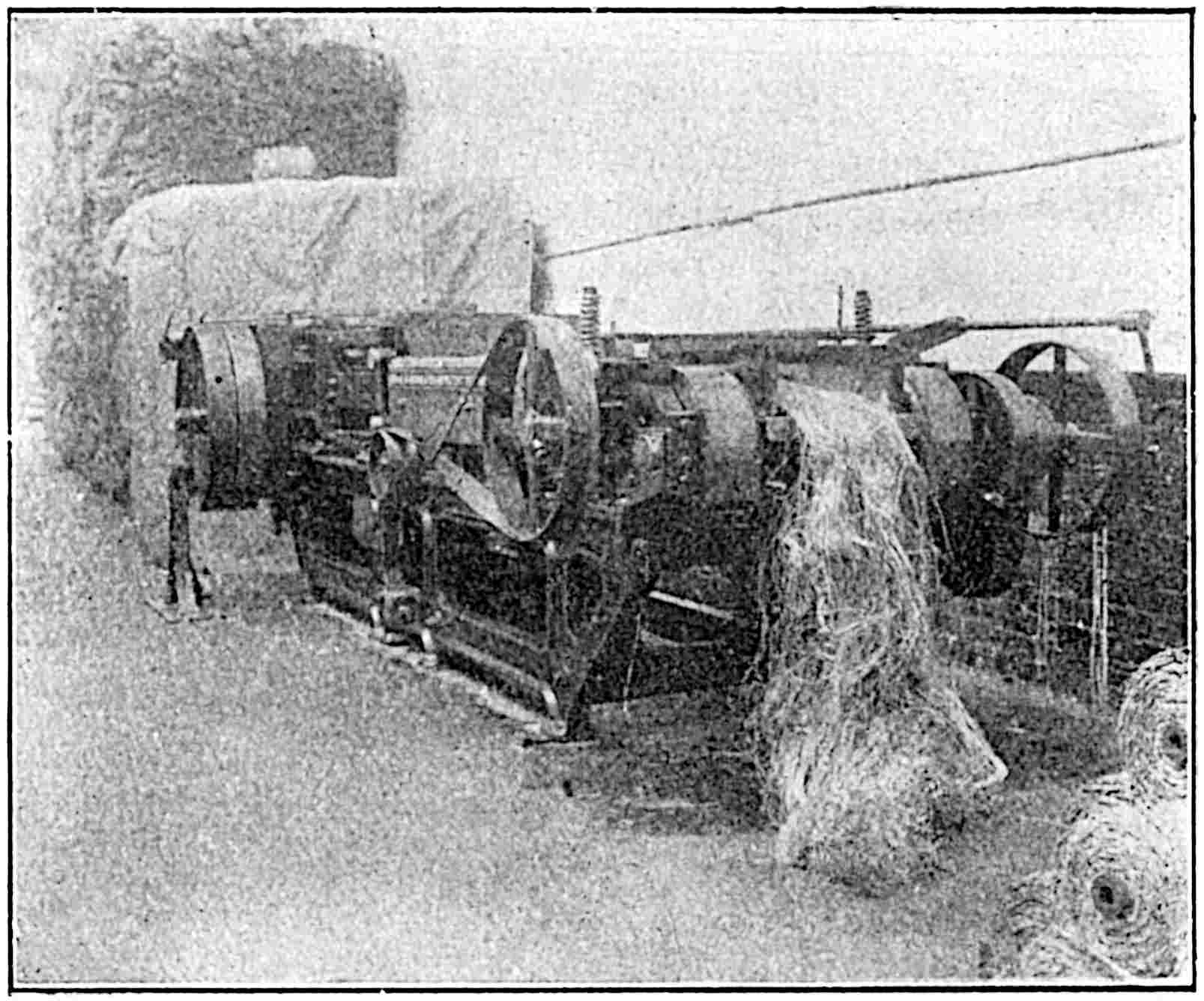
The heads of material are split up into suitable and uniform stricks, and when various classes are to be mixed it is essential that proportionate quantities should be drawn from the various bales in the “batch” or blend, and fed proportionately and uniformly on to the feed sheet of the machine. The feed sheet conveys the stricks slowly towards and ultimately between a pair of retaining and feed rollers, and when the material emerges from these rollers it is acted upon by a series of large hackle pins fixed in a chain of fallers or bars. These pins move at twice the speed of the feed and retaining rollers, and this relative movement enables 88the pins to hackle and open out the stricks. The partially-hackled stricks are now conveyed to a second chain of fallers and hackles which move at a much greater speed than that of the first hackles; it is here where most of the drawing takes place, and the material as it leaves these hackles is in the form of a thin sheet of fibres which enters a pair of drawing rollers. Finally, the material is delivered on to the floor in the form of a sliver and at the opposite end of the machine.
The bundles of sliver are conveyed to another machine, termed the intermediate machine, where further processes of equalization and drawing take place. In this, and in any subsequent machine of the same type, of 89which there may be three or four, the slivers are fed as illustrated on the left of Fig. 26, while several lengths of slivers appear in the foreground. After the drawing and hackling operations, the sliver is delivered as illustrated. These processes prepare suitable slivers for the remainder of the operations which are somewhat similar to those which are used for the soft fibres, although the “reach” in the machines for the hard fibres is very much longer than that necessary for the soft fibres. In the final preparing machine, the sliver is delivered into sliver cans which are then taken to the automatic spinning frame.
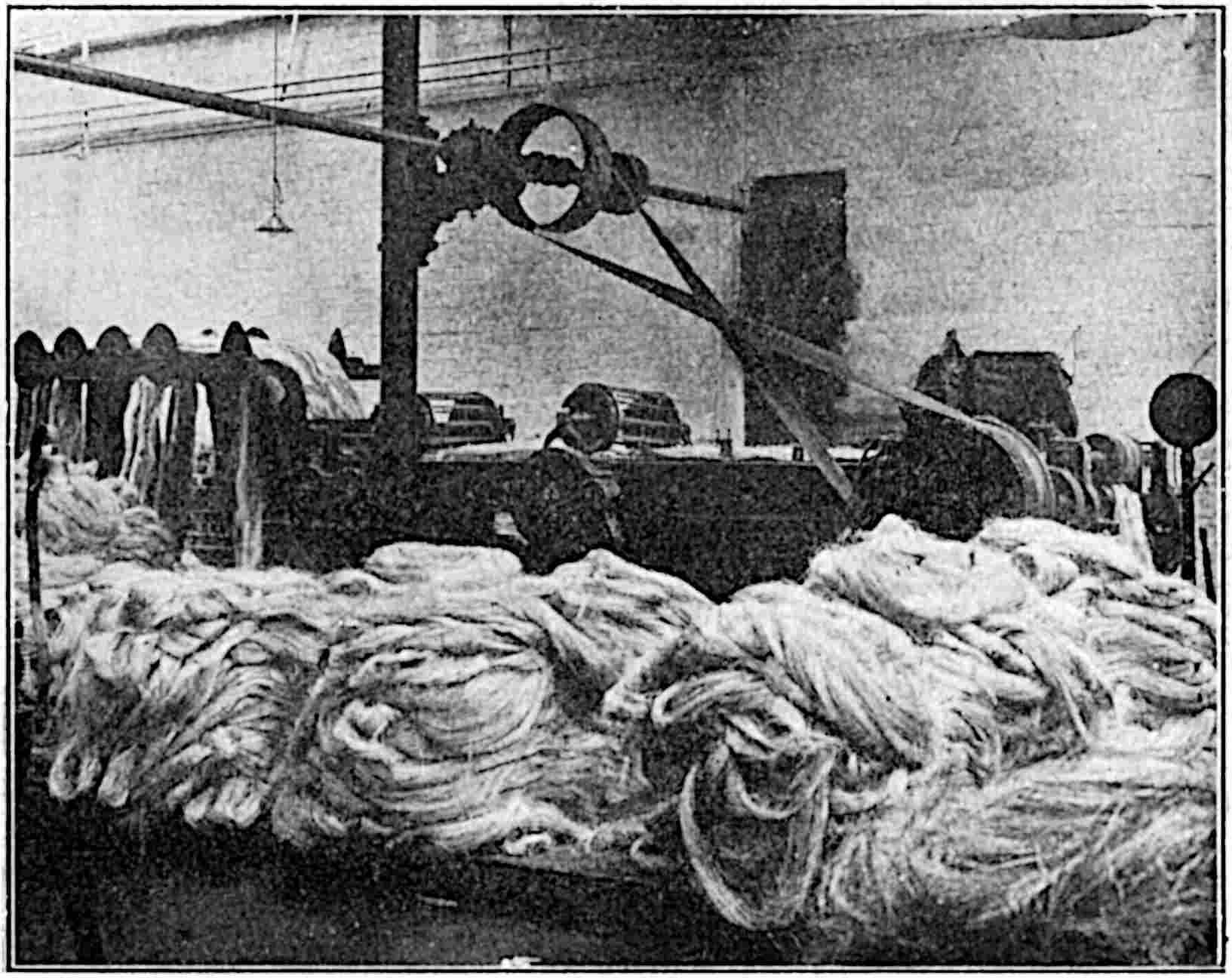
Automatic Spinning Machines.—A row of automatic spinning machines is illustrated in Fig. 27. The slivers 91from the last drawing frame are placed at the feed, one sliver can with its length of sliver for each machine. The sliver is passed through the first conductor, situated about a yard above the sliver can, and then between a pair of feed rollers seen to the right of the machine. From here the sliver is deflected to the proper bell-mouth conductor and to the long stretch or reach of gill pins shown clearly in the view. On emerging from the gill pins, the sliver passes through a nipping die and thence to the enclosed flyer from which it is wound on to the bobbin.
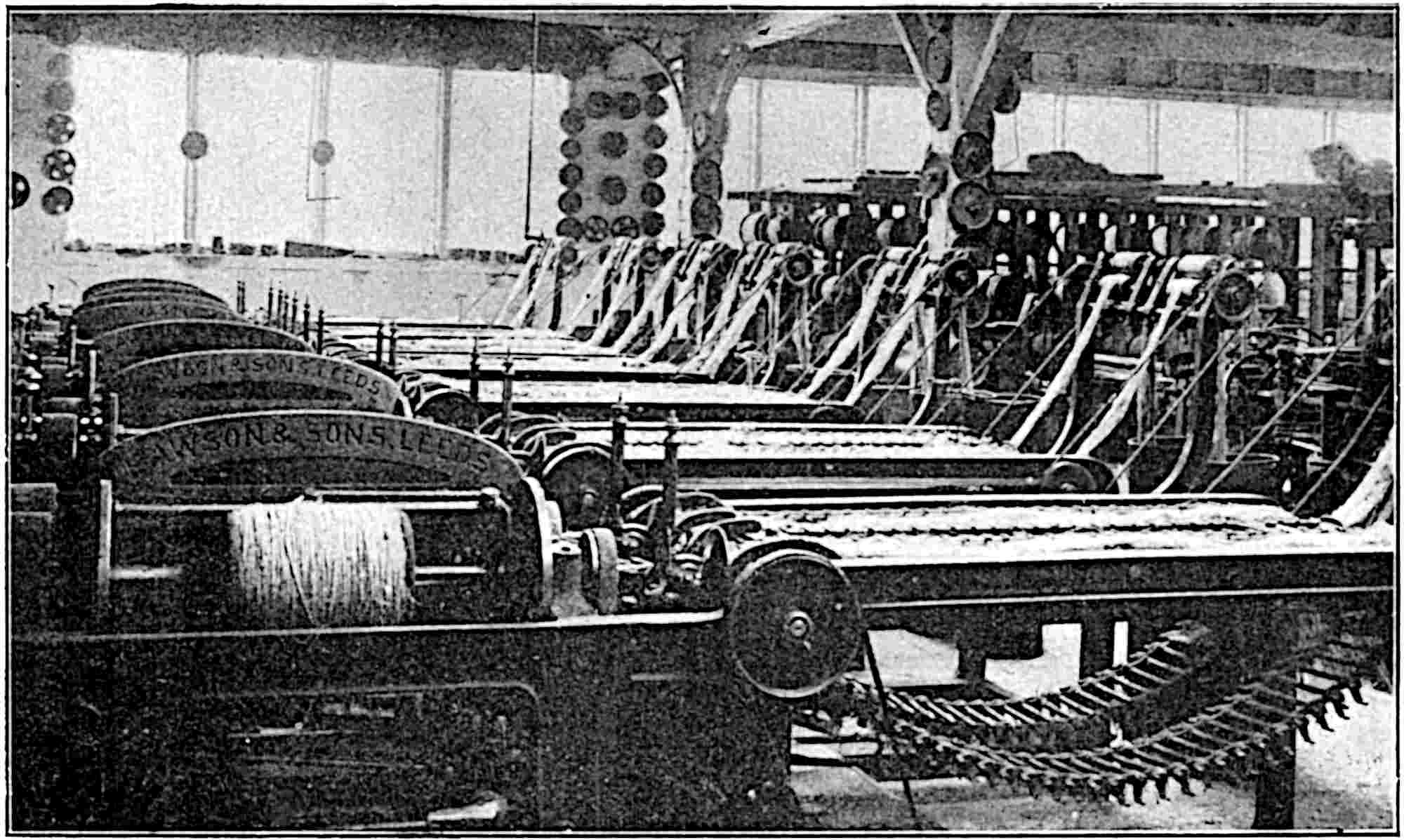
The drafting is accomplished by a series of rollers or pulleys which draw the fibres through the gill pins and the nipping die, while the twist is imparted as usual by the flyers which revolve at about 1,400 revolutions per minute. The flyers are now enclosed in a safety cage of about the same width as the name plate.
The yarns thus spun are built upon large steel-ended bobbins which, when filled, may be conveyed direct to the transferring or warping machines where the yarns are prepared for further treatment, if and when any further treatment is necessary, or to the rope machines. Thus, if the yarns are to be made up into a tarred rope, it is necessary to prepare them into a suitable form for the tarring operation. This usually takes the form of a warp, and such warps are most satisfactorily made on a warping mill or winding reel. It is usual to run twelve threads from twelve bobbins and to make the warp a suitable size by continuing the operation of warping in the same way as is done for warps which are to be woven in a loom.
The warp is then passed through a tarring machine in which the tar, usually Russian or Swedish, is kept warm during the operation. After the necessary amount of tar has been applied, it is usual to store the warps 92of yarn for a lengthened period, say up to six months, to condition them. The individual yarns from these warps are then rewound on to twelve large bobbins in what is known as a 12-bobbin vertical spindle-winding machine.
There are many instances in which yarns made by the foregoing operations are incorporated in twines, cords and ropes, while, on the other hand, special types of machinery are utilized to manufacture certain grades of such goods with an entirely different system of machinery. It is in connection with the latter branch that this chapter will for the most part treat, but, before dealing with these machines for specific purposes, we might just say that there are huge quantities of yarn spun by the methods already described, and the single yarn so spun is then twisted so that the resulting compound may contain two single threads twisted together, or any other greater number twisted either in one operation, or two or more separate operations, to obtain the desired type of cordage. In many cases the yarns have to be bleached before they are twisted, and Fig. 28 illustrates the drying of bleached yarns.
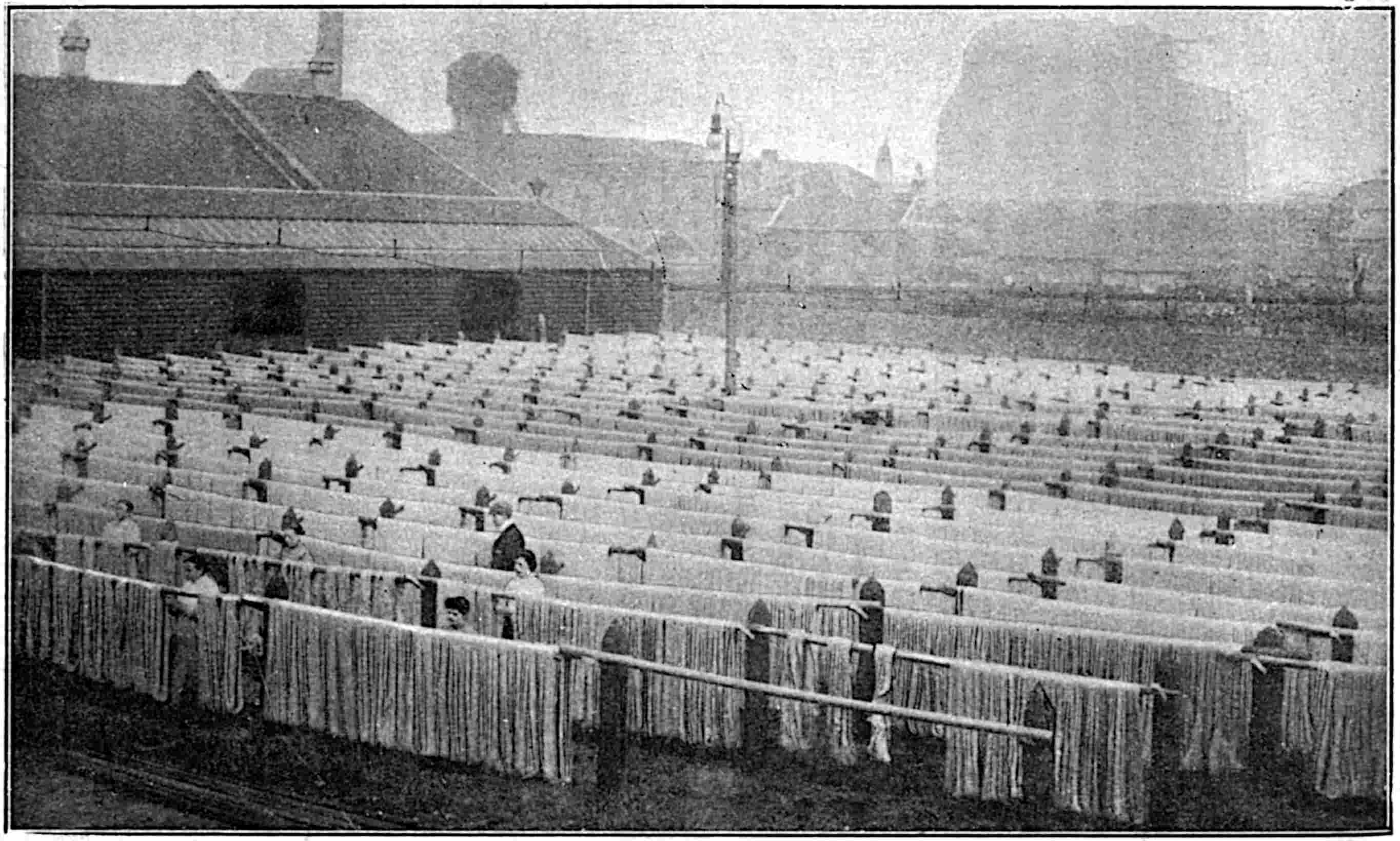
The terms twine, cord and rope all indicate to the textile technologist a multiple structure, that is, an article in which two or more single threads are united by the process known as doubling, folding or twisting.
Thus, in the manufacture of twines, of which there is a great variety, the process is a comparatively simple one. A number of bobbins are arranged on pins in a creel somewhat similarly to those illustrated in the spinning frame in Fig. 24. The requisite yarns, from 2, 3, 4 ... n bobbins, for the type of twine in process are led from the bobbins through an eye or guide or through a “register plate,” then between a pair of 94drawing rollers, and thence to the flyer and spindle as in the spinning operation. As the spindle and flyer rotate, the group of single yarns are drawn through the guide or eye, or through the register plate by the drawing rollers, and the necessary amount of twist applied before the finished product is wound on to the bobbin. The amount of twist, or the technical term “twist per inch,” is fixed by the speed of the spindle and the delivery of the yarn by the drawing rollers. In other words we have—
| revs. per min. of spindle | = | the number of turns per |
| delivery of twine in in. per min. | in. or the twist per in. |
There is this difference between spinning and doubling or twisting; when a thread breaks in spinning, the supply of yarn to the bobbin ceases, and the production from that spindle stops until the broken thread is repaired; on the other hand, when two or more threads are being twisted together and wound on to a bobbin, it is evident that if one thread breaks the supply is not stopped entirely, but the product is defective because it is short of that yarn. In order to prevent the production of faulty goods and to minimize waste, it is a common practice to introduce delicate mechanical parts to such frames, the function of which parts is to stop the delivery of yarn to any spindle in connection with which any of the constituent threads are broken. A frame so fitted is said to have an “Automatic Thread Stop Motion.”
In many cases the twines made by the above process are taken to another machine in which a number of bobbins are again arranged on pins, the twines passed under rollers and immersed in polishing mixtures of starch or size contained in troughs or boxes. A quantity of the size adheres to the twines as they pass through it, and revolving brushes are used to remove the excess 96of size and to clean the twines. These operations are repeated a few times and ultimately the twines so starched, cleaned and polished are led over drying cylinders in front of which are placed rollers covered with suitable material, usually coir yarns. These rollers rotate at a high speed, and sometimes wax is applied to the coir yarn-covered rollers, so that the twines are dried, polished and finished simultaneously before they leave the hot cylinders to be wound on to a second set of empty bobbins. This machine is usually termed a “bobbin to bobbin polishing machine,” and the bobbins upon which the twine is finally wound are frictionally driven because the delivery of twine is constant. In this way the requisite finish or polish is applied to the surface of the twine, and this gives the twine the smart appearance which makes it quite attractive.
In the operation of twisting single yarns, that is, in the roving frame and in the spinning frame, it is usual to impart what is known as a “right twist.” Thus, if one looks down on a spinning or roving spindle and the direction of rotation is clockwise, then the twist imparted is right hand. On the other hand, if, when viewed from the same position, the spindle rotates counter-clockwise, the definition is “reverse” or left-hand twist. When two single threads of right-hand twist are combined in twisting as in the formation of the above-mentioned twines, it is usual for the doubling or twisting spindles to rotate counter-clockwise. This is done for practical reasons which need not be discussed here, but, although this is the usual way, there are cases in the twisting of textile threads where two right-hand twists are combined with the same direction of twist. Some such definition as the above will help considerably to elucidate the structure of more complicated multiple-twist cords.
97Cords.—In the manufacture of cords, three or more twines are combined. Thus, if three twines, each of reverse or left-hand twist and made from two single yarns of right-hand twist, are combined together by a further process of twisting, it is usual to apply a right-hand twist to these three two-ply twines. When treated in this way, the finished article is termed a cord which is “cable laid.” And, in general, in the twisting of such cords, each successive twisting operation is in the opposite direction to that which immediately preceded it.
Whip-cords, fishing lines and window-blind cords are typical of this structure which, in general, involves the use of complicated machinery or else a long rope walk. The single yarns are first made into twines and finished as already described; afterwards the necessary number of twines to form the cable-laid cord are united.
The operation is a costly one when compared with the simpler process of twine making, but the cable-laid cord is a much more handsome product than the twine, and is admirably adapted for purposes where a smart compact and ornamental structure is desired or necessary.
Box Cord.—Box cord is a very simple form of cordage, the method of manufacture being quite different from that of the foregoing laid cords. In the box-cord process there are two distinct groups of twisting operations conducted simultaneously. The single threads, of which there may be from two to eight, receive the necessary additional twist by a corresponding number of flyers which differ in shape, however, from the ones in roving and ordinary spinning in that they are known as enclosed flyers. While these individual threads are being twisted, the several yarns converge towards, and pass direct to, the eye of another enclosed flyer which completes the process by twisting the component threads 98in the opposite direction to that imparted to the single threads by the two to eight different flyers. It should be mentioned that the building of the completed box-cord on the bobbin is accomplished by suitable mechanism attached to the flyer.
The machine is comparatively simple, and the attendants need little experience beyond that of detecting broken threads and repairing them. It need hardly be pointed out that the omission of a thread from the requisite number in the group for the finished cord is a fault the prevention of which constitutes one of the chief duties of the attendant. The finished product is termed two-ply, three-ply, ... eight-ply box-cord according to the number of single yarns which are utilized. Practically all classes of fibre are used in the manufacture of these goods, and this method of twisting is largely adopted for the making up of comparatively light cords from fairly heavy sizes of yarn. The product is used extensively for tying boxes and large packages and thus serves the purpose of a light rope which is a more expensive article.
Plaiting or Braiding.—Special classes of lines and cords are now made on a machine of an ingenious design. One of the advantages of this machine is the fact that great lengths of line can be made; indeed, there is practically no limit to the length which may be made beyond that of the difficulty of handling the huge size of the finished product.
The machine, which is complicated and costly in its upkeep, is used extensively for the production of log lines, sash cords, and a large variety of blind cords. The requisite number of threads for the cord are wound on a suitable number of bobbins, and the latter are placed in carriers in the machine. The yarns or twines are passed over or across each other in such a way 99that they are locked in position and in the well-known plaited form which is characteristic of this class of goods. This scheme of interlocking is formed by an even number of groups of threads, usually eight or more, and the movements of these groups, or rather the bobbins which contain them, are practically identical with the familiar “grand-chain” in circle dances practised by children and also by grown-up persons. Alternate bobbins move sinuously round a circle in one direction, while the remaining alternate bobbins move similarly in the opposite direction. Each bobbin passes those in the other group first on the left and then on the right of a circle whose path is the centre of the two sinuous paths described by the two sets of bobbins.
The continuous movements of the two sets of bobbins in each machine form the elegant cord which, when plaited, passes through a guide eye in the centre of the circle but in a higher plane. From this eye the cord rises to a pair of hauling-winch pulleys around which it passes a few times forming the figure 8. Finally, the cord passes between a pair of delivery rollers into a large box at the back of the machine. The hauling-winch pulleys and the drawing rollers, which combined give the necessary firmness, are driven positively and accurately so that their surface speeds may coincide with the amount of cord which is formed at the guide eye.
A considerable quantity of the smaller-sized ropes are now made on what are termed “house machines.” These machines perform the same function as those in the rope-walk but they occupy a much smaller space; they are adapted to deal with a great range of sizes although, in general, it is not necessary to use one machine for a large range of work; there is such a variety of ropes in use that in a well-equipped rope works it is possible to keep each machine almost constantly on ropes within a small range of size. These remarks refer, as indicated, to ropes which come within the limit of, say 2 to 3 in. in circumference. In the manufacture of the larger sizes of ropes, it is usual to use two distinct machines, one termed the “strander,” and the other the “closer,” and, although the house-machine made ropes are often considered inferior to those made in the rope-walk, many of the objections urged against the untarred ropes made in the house-machine are more imaginary than real.
Fig. 29 is illustrative of a number of machines of a type used for the making of ropes in which twelve to forty-five threads may be combined in one operation during the manufacture of a three-strand or a four-strand rope. The bobbins are placed in creel flyers of which there may be three or four according as the rope is to be a three-strand or a four-strand one. The creel flyers are composed of two parts, one of which carries the bobbins, and the other carries the hauling and twisting gear. All the three or the four strands are made at the same time; when formed, they leave their 101respective flyers and converge towards the top and the die or central tube where they are formed into a rope by the proper degree of twist according to the purpose for which the rope is to be used. Finally, the finished rope is drawn forward by a series of hauling pulleys which also conduct the rope to the winding-on reel or bobbin, and by suitable mechanism the rope is wound into a temporary form of coil. As the bobbins are filled with rope they are removed from the machine and conveyed to special coiling machines where they are measured when necessary as they are made up into coils suitable for the particular purposes desired. A common length of coil is 120 fathoms.
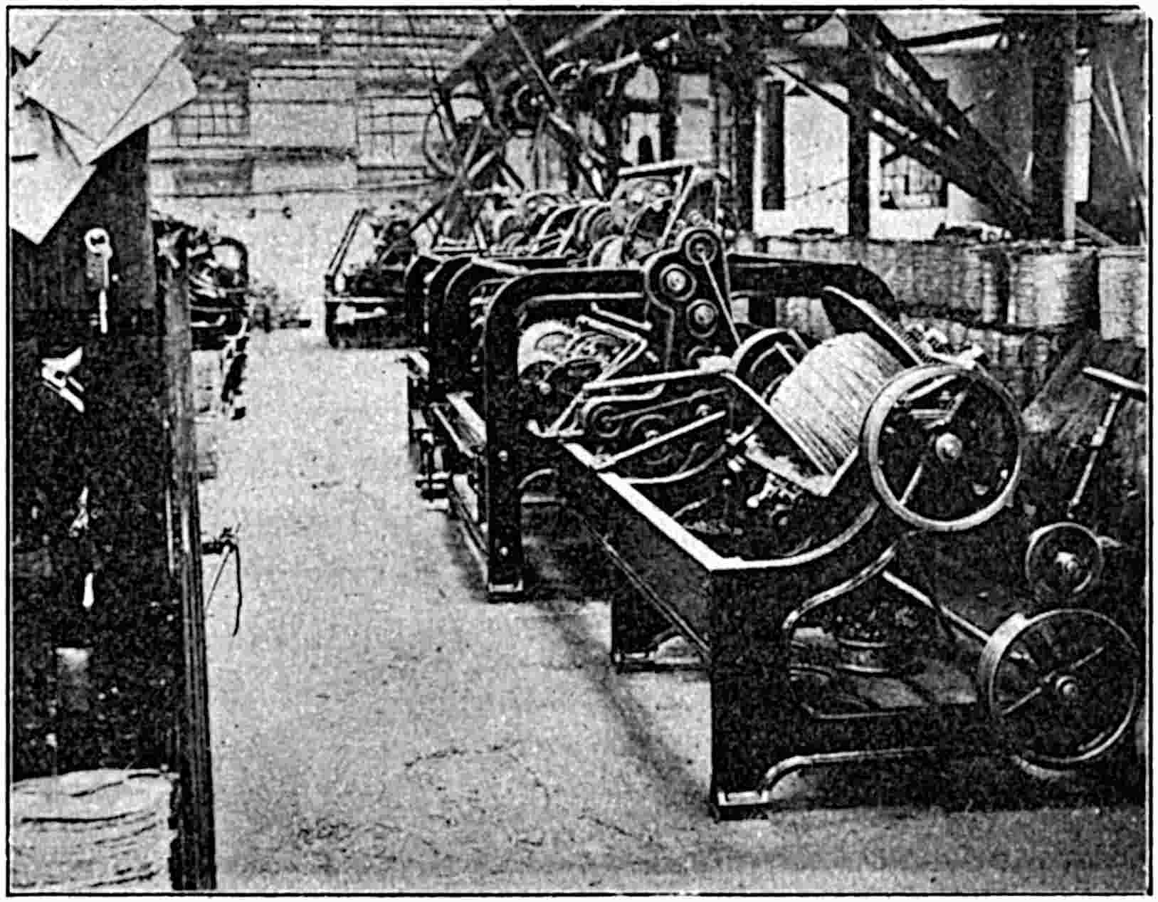
Although the various house machines represent the latest developments in the art of stranding and closing—the 102two essential operations of rope making—a modern rope and cordage works is provided not only with the various machines which have been illustrated and described, but also with a well-equipped rope-walk so that the products may include a great variety of cordage from the finest lines to the mammoth ropes for ships, steamers, harbours and heavy hauling purposes generally.
The combination of the house machines and the modern rope-walk makes present arrangements very complete when compared with the old type of rope-walk, but the apparatus employed in these old rope-walk machines embodies all the principles of construction which are present in the new machines for the same class of work.
Rope-walks are, naturally, long, narrow buildings because the full length of the rope is in one stretch.
The work which is conducted in such places and the type of building is admirably portrayed in the first three verses of Longfellow’s poem—
THE ROPE-WALK.
In that building long and low,
With its windows all a row,
Like the port-holes of a hulk,
Human spiders spin and spin,
Backward down their threads so thin,
Dropping, each, a hempen bulk.
At the end an open door;
Squares of sunshine on the floor
Light the long and dusky lane;
And the whirling of the wheel,
Dull and drowsy, makes me feel
All its spokes are in my brain.
As the spinners to the end
Downward go and re-ascend,
Gleam the long threads in the sun;
While within this brain of mine
Cobwebs brighter and more fine
By the busy wheel are spun.
103At the top of the rope-walk is a stand or bank which contains the bobbins of yarn, and this yarn may be dry or tarred according to requirements. The bobbins are arranged on pins and the necessary number of yarns for each strand are drawn from the bobbins and passed, in their proper order for ensuring a uniform strand, through a number of holes in a “register plate” immediately behind the machine. In a modern machine any number of strands up to six can be formed at the same time, and hence there will be six register plates for the yarns. For the larger-sized ropes only one strand can be drawn out in one operation.
A machine termed a “traveller,” is employed to draw out the strands, and this machine is provided with a series of hooks as well as a central spindle. The strands may be attached as required either to the hooks or to the spindle. A rope-driving gear causes this traveller to move on rails down the walk and for the distance required, and it will be evident that as the traveller recedes from the bank it will draw the groups of threads from the bobbins and through the register plates; at the same time the several hooks are caused to rotate, and thus each strand is twisted and hauled simultaneously.
When the traveller has moved backwards or downwards for the necessary distance to form the length of strand, the strands are removed from the hooks and attached to suitable supports until a sufficient number has been made for closing or laying-up.
To form the strands into a rope, it is essential to use a fixed or stationary machine along with the traveller and a top-cart. The stationary machine is substantially built, and, inter alia, is provided with a central spindle around which are grouped a set of hooks—usually in sections of two circles. Two wheels on the central spindle 104drive a number of pinions, one behind each hook, the ratio of one wheel to half the pinions is 34 to 16, while the ratio of the other wheel to the other half of the pinions is 54 to 11. Thus, the revolutions may be—
| 1 | to | 1 | when the strand is on the central spindle, | ||
| 34 | to | 16 | or | approx. | 2 to 1 when on large hooks, and |
| 54 | to | 11 | „ | „ | 5 to 1 when on small hooks. |
When the necessary strands to form the rope are stretched between the stationary machine and the traveller, an extra amount of twist is imparted to each strand, an operation which is termed “hardening the strand”; the amount of twist can be judged only by past experience, although it is common to give instructions in the words “harden so many fathoms”; at other times the strands are hardened until the threads form a desired angle. In all cases the strands should be twisted equally so that the same tensile stress is on each strand. After this twist has been applied, all the strands are placed either on one of the hooks or on the central spindle of the traveller. A top-shaped block is put into position inside the three strands—this top is in full view in Fig. 30, which, by the way, illustrates the laying of a 28-in. circumference four-strand hawser with a central core—and the machines started for a few revolutions. When the first make of the rope is formed, the top is brought back to its proper place, a few pieces of rope, termed tails, are placed round the newly-formed portion of the rope, and these may be collected and held in position by a bar as shown; one of these tails was removed when the photograph was taken in order to show the finished part of the rope between the top-cart and the traveller. The traveller is now braked to keep the rope taut while the rope-maker lays the strands, the hooks of the stationary machine at the top of the walk as well as the hooks on 105the traveller being rotated meanwhile at a speed which is suitable for the make or lay of the rope. The hooks in the two machines rotate relatively about 7 to 9 or 7 to 11.
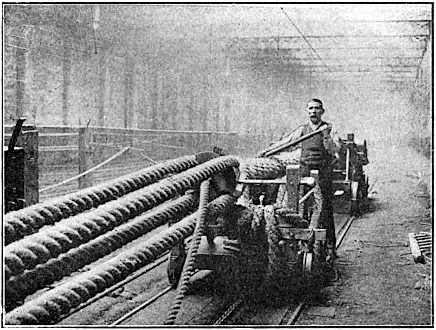
When a hawser or cable-laid rope or a “trawl warp” is desired, the formed ropes are again placed in position, and the whole routine repeated, while if the warp is to consist of more than three strands, a heart must be inserted, as exemplified in Fig. 30, upon which to lay or build the strands. It will be understood that the view in Fig. 30 is the interior of “a rope-walk,” and that the operative is looking towards the top of the walk where the stationary machine is situated.
After the laying is completed, the finished rope must be made into a coil ready for transportation. The coiling machines are often in close proximity to the 106house machine or the rope-walk, and for the coiling of such ropes as that illustrated in Fig. 30, it is obvious that the machine must be of substantial build. When such a large rope is complete and ready for despatch, it resembles the 18-in. circumference mooring rope in Fig. 31; this rope was 90 fathoms long and two tons weight, and was coiled in about ten minutes by a machine specially designed for the purpose.
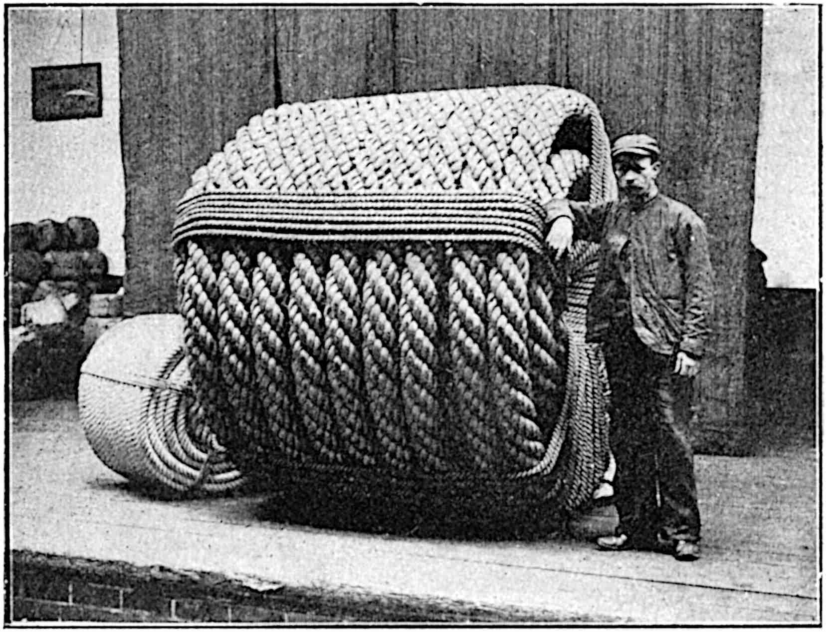
Rope driving has practically revolutionized the construction of modern mills since ropes are used not only as a direct drive from the rope pulley on the engine or motor shaft, but at many intermediate places, and have replaced many installations of wheel-gearing. These mill-driving ropes, which are invariably from 1½ to 2 in. in diameter, are made extensively of cotton, hemp or 107manila. In exceptional cases more than forty such ropes are used on the same pulley. The frontispiece illustrates a rope drive in which seven ropes each of 1¾ in. diameter, are utilized on the shaft of a motor for conveying the motion to a mill shaft seen in the distance. Other ropes are seen in the next rope alley. Somewhat similar ropes, but of a smaller diameter, are used for hauling in the baling press illustrated in Fig. 15.
There are several methods of numbering yarns, most of which involve a direct relation between the weight and length. Thus, to quote six of the most widely-practised methods in the textile industry we have
| Silk: | count no. | = | the no. of | hanks | of | 840 | yards | each | in | 1 | lb. |
|---|---|---|---|---|---|---|---|---|---|---|---|
| Cotton: | „ | = | „ | hanks | „ | 840 | „ | „ | „ | 1 | „ |
| Wool: | „ | = | „ | skeins | „ | 256 | „ | „ | „ | 1 | „ |
| Worsted: | „ | = | „ | hanks | „ | 560 | „ | „ | „ | 1 | „ |
| Linen: | „ | = | „ | leas | „ | 300 | „ | „ | „ | 1 | „ |
| Jute: | „ | = | the weight in lbs. of 14,400 yards | ||||||||
Hemp is sometimes reckoned according to the linen system and sometimes by the jute system.
An entirely different method of counting or numbering obtains in regard to ropes. The system of yarn numbering for ropes depends upon the number of single yarns or threads required to make one strand of a 3-in. 3-strand rope. Thus, if 25 yarns are required to form such a strand, the yarn is 25’s, while if 30 yarns were required for the same thickness of strand, the yarn would be 30’s, and so on. The tube through which the yarns are drawn is nearly half an inch bore.
If the yarn number is multiplied by 5, the product represents the number of yards of yarn in 1 lb. Thus, in the above 25’s yarn there are
25’s × 5 = 125 yd., or 375 ft. per lb.
Ropes are usually designated by their circumferences in inches, and also by the number of strands neglecting the heart if such is required.
It is essential in modern times that goods which are placed on the market should be as attractive as it is possible to make them, and cordage forms no exception to this rule. The acme of attraction may be said to have been reached when a sale is effected more from appearance than from any immediate want, and this is the ideal to be aimed at. No detail which will make the goods attractive or memorable should be omitted. Carelessly made-up goods are quickly noticed, and however high may be the quality of the article, an indifferent make-up creates an unfavourable impression which is difficult to remove.
Little things, insignificant in themselves, often form the nucleus of great undertakings. Mnemonic titles, trade names, distinctive labels and the like are all adopted to safeguard the interests of the maker, to guarantee his products, to spread his fame, and to keep his goods constantly in the mind’s eye of the purchaser.
Whilst no great effort is necessary to parcel up small articles in an attractive form, it seems hardly possible to deal with bulky articles with the same degree of success. Nevertheless, several of these heavy and unhandy articles are elegantly made up as is emphasized by the coils in Fig. 31. This is the usual way of making up ropes, and the size of the coil depends partly upon the length of the rope, partly upon the use to which it is to be put, and partly upon the thickness. If the ropes are to be cut up into definite lengths, the coil 109will be a multiple of that length; if otherwise, a common length of rope is 120 fathoms as already stated.
The smaller coils, and the better grades of larger coils, are often enclosed in paper, while the larger ones are covered with wrappers of suitable texture to ensure the arrival of the ropes in good condition at their destination. The coils themselves are securely bound as exemplified in Fig. 31 to prevent the displacement of the structure during transit or handling, and, in addition, many of these large and valuable ropes are entirely covered by a cheap rope binding.
A large quantity of ropes, cords and twines are made into hanks or “rands,” as they are termed, on a special machine. For short lengths this method of making up is very compact, very neat and very convenient for marketing.
Binder twine is first made up into standard size balls which must fit the boxes on the reaping and binding machines; afterwards they are packed in bales ready for despatch.
Other varieties of twine are made up in the same shape of balls as above, but the sizes of the balls depend upon many circumstances. Large quantities for the retail trade are made up into convenient sizes to suit the twine boxes, and again many are made to a specified weight.
It will thus be seen that a series of balling machines will be required to deal with the making up of the twine in this form. These machines make neat and attractive-looking balls, the weight of which may vary from 2 oz. to 28 lb. each.
The mechanism by means of which the yarn is built up into balls is at once elegant and ingenious, and the made-up ball is quite satisfactory if when commencing to use the twine, the end is withdrawn from the right 110end of the ball. A ticket with the words “pull out this end” is often attached as a guide. If the twine is drawn from the wrong end of a ball, the continual difficulty experienced in withdrawing the twine will be always remembered; on the other hand, if the twine is drawn out at the proper end, the correct running of the twine will enable the attendant to complete his parcel tying with the minimum of trouble and time, and enable him to give attention to other work in hand.
This inconvenience is obviated by a comparatively recent introduction in winding which makes an elegant cylindrical structure termed a roll. This popular and efficient mechanism is the Universal Winding Machine, the various makes of which enable rolls of from 2 oz. to 72 lb. to be made perfectly. The rolls are so attractive, compact, economical and easily handled that one would not be surprised to see a much more extended application of this useful form of package.
For shops and similar places, the smaller balls and rolls are made up in paper parcels of about 12 lb. each. The larger balls and rolls may be made up separately or in convenient numbers. Sewing threads and yarns may be made up in small balls, but a more common and neater arrangement is to make them up on reels or in rolls. Neatness, facility for use, and suitability for intended purposes are the main points to be cultivated in order to secure and retain business.
THE END
Printed by Sir Isaac Pitman & Sons, Ltd., Bath, England
v—(1465f)
Stephen Cotton & Co. LTD.
Brookfield Foundry
Belfast
Flax and Hemp Textile Machine Makers, Iron and Brass Founders
SPECIALITIES:
¶ Patent Automatic Screwing and Changing Apparatuses for Hackling Machines. Brush and Doffer Hackling Machines. Stripper Rod Hackling Machines. Hand and Power Reels, with Straight and Cross Winding. Flax and Hemp Cutters. Bundling Presses. Spinning Frames. Spindles and Flyers.
PARTICULARS ON APPLICATION
PITMAN’S
Common Commodities and Industries Series
Some Recent Additions. Each 2/6 net
Complete List on application
SIR ISAAC PITMAN & SONS, LTD., 1 AMEN CORNER, LONDON, E.C.4
COMMON COMMODITIES AND INDUSTRIES SERIES
Each book in crown 8vo, cloth, with many illustrations, charts, etc., 2/6 net
OTHERS IN PREPARATION
Transcriber’s notes
The illustrations have been moved to appropriate paragraph breaks. References to their page numbers in the List of Illustrations and the Index have been adjusted accordingly.
The footnotes have been renumbered and moved to the end of the chapter in which they occur. Index entries may refer to text in a footnote.
Some index entries have been changed where it seems the original page number was incorrect.
The reference to Fig. 10 on page 51 originally read Fig. 12.
The advertisements have been moved to the end of the book.
Obvious typographical errors have been corrected. Inconsistent hyphenation has not been changed.